6
3.3 Outputs
3.3.1 Abbreviations
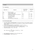
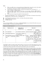
Abbreviation Stands
for Programming
via Fct. No...
Description
See Sect....
EC
EMC
F
F
100%
I
I
0%
I
100%
Q
0%
Q
100%
Electronic counter
Electro-mechanical counter
Frequency (Pulse) output
Pulses for Q = 100 % flow rate or pulse value
Current (analog) output
Current at 0/4 mA flow
Current at 20 mA flow
0% flow rate
Full - Scale range, 100 % flow rate.
---
---
1.4.X
1.4.2
1.3.X
1.3.3
1.3.4
1.1.2
---
---
6.1 + 6.2.9
6.1 + 6.2.9
6.1 + 6.2.8
6.1 + 6.2.8
6.1 + 6.2.8
-
6.1 + 6.2.4
3.3.2
Current (analog) output I
The current output is galvanically isolated
from all input and output circuits but
not
from frequency
output F. Therefore only one grounded receiver instrument may be connected to either current output I or
frequency output F.
·
·
·
·
All functions and operating data are programmable,
see sections 5, 6.1 & 6.2.8.
Factory-set data and functions are listed in the enclosed ‘Configuration Sheet’ on settings.
This can also be used to record any changes made to the operating parameters.
Max load at terminals
5/6 for I
100%
(
Fct. 1.3.4
)
:
Max. load Kohms =
]
[
14
%
100
mA
V
(e.g. 0.7 K ohms for I
100%
= 20 mA)
[
]
I
Error annunciation
programmable to 2 mA or 22 mA
(
Fct. 1.3.2
)
·
·
Connection diagram
Refer to Section 3.3.4


