2
. Installation in the pipeline
2.1 General
1
.
Flow direction and meter position
·
·
·
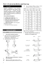
Flow must always be in the direction of arrow,
bluff side of vortex-shedding body facing
incoming flow i.e. upstream side.
Vertical pipe run : upward flow direction
Horizontal pipe run : see below
2.
Difference between inside diameter of primary
head and pipeline
DN
F
Meter size of primary head in mm or inches.
Inside diameter of primary head in mm or inches.
Part A System installation and Start-up
DF
Max. allowable difference between inside
diameters of primary head and pipeline.
1. Description
KHRONE MARSHALL Vortex Flowmeter
operate on the Karman vortex street principle to
measure volumetric flow rate of gases / steam
and liquids. VFM computes normalized
volumetric and mass flow rates from operating
Pressure and Temperature values, or from density
values. Temperature sensor is standard &
pressure sensor is optional to provide an on-line
P&T compensation.
Items included with shipment
·
·
·
·
·
Compact Vortex Flowmeter
Installation and operating instructions
Mounting bolts, washers, nuts
Plastic cover wrench for electronic housing
·
Optional upstream & downstream pipes
·
Programming chart indicating factory
configuration settings.
Gaskets between primary head and pipeline.
Provided by customer
·
All cables for electrical connections.
SIZE
f
Df
SIZE
f
Df
DN
(mm)
mm
(inch)
mm
(inch)
DN
(inch)
mm
(inch)
mm
(inch)
10S
8.9
(0.35)
0.4
(0.016)
3/8"S 8.9
(0.35)
0.4
(0.016)
10
12.6
(0.50)
0.4
(0.016)
3/8" 12.6
(0.50)
0.4
(0.016)
15
14.9
(0.59)
0.4
(0.016)
1/2" 14.9
(0.59)
0.4
(0.016)
20
20.9
(0.82)
0.4
(0.016)
3/4" 20.9
(0.82)
0.4
(0.016)
25
28.5
(1.12)
0.4
(0.016)
1" 26.7
(1.05)
0.4
(0.016)
40
43.1
(1.70)
0.4
(0.016)
1/5" 40.9
(1.61)
0.4
(0.016)
50
54.5
(2.15)
0.6
(0.024)
2" 52.6
(2.07)
0.6
(0.024)
80
82.5
(3.25)
0.6
(0.024)
3" 78
(3.07)
0.6
(0.024)
100
107.1
(4.22)
0.6
(0.024)
4" 102.4
(4.03)
0.6
(0.024)
150
159.3
(6.27)
0.8
(0.031)
6" 154.2
(6.07)
0.8
(0.031)
200
206.5
(8.13)
1
(0.039)
8" 202.7
(7.98)
1
(0.039)
Ensure that the bore of locating pipes are smooth and without
deposits or scaling of welding beads.
3. Straight, unimpeded inlet and outlet runs
D=Meter size (Nominal Dia. DN)
INLET OUTLET
1


