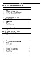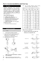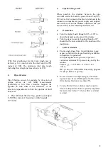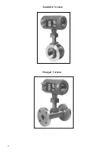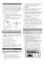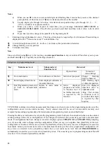
VFM 5090(I) may be supplied with an optional
pressure sensor. This sensor is typically a strain gauge
type and located in the primary assembly as shown in
the figure below. Thus the sensor also provides an
accurate measurement of pressure
of the process fluid.
Flowmeter will continuously measure medium
pressure -
·
·
·
To display the medium pressure value
To provide an on-line P&T compensation along
with T sensor for mass and normalized volumetric
flow computation.
To monitor whether the medium pressure is within
the user specified operating pressure limits.
To determine the pressure of the medium (e.g. to feed
the pressure value in VFM for an off-line P&T
compensation for mass or normalized flow
computations), suitable measuring point must be
provided near the flowmeter.
Location upstream of flowmeter
Min. distance : 20*DN (DN = meter size)
Location downstream of flowmeter
Min. distance : 5*DN (DN = meter size)
Allowance must be made for the pressure drop in the
flowmeter as correction value for operating conditions
prevailing upstream of the flowmeter.
3. Electrical
connection
3.1
Installation location and cable diameter
Location
·
·
·
·
·
·
·
·
·
·
·
Do not expose the compact flowmeter to direct
sunlight. Install a sunshade if necessary.
Do not expose to intense vibration. If necessary
support the pipeline to the left & right of the flow
meter.
The rotating design of the housing makes it easier
to connect the two cables for power and outputs to
the terminals in the rear terminal box.
2.4.2 Pressure measurement with built-in sensor
Cable diameter
To conform to protection category requirements,
observe the following recommendations
Cable diameter : 8 to 13 mm (0.31” to 0.51”)
Enlarge the inside diameter of the Screwed conduit
entry by removing the appropriate onion ring(s)
from the seal,only if cables have extremely tight
fit.
Fit blanking plug PG 16 and apply sealant to
unused cable entries.
Do not kink cables at conduit entries.
Provide water drip point (U bend in cable).
Conduit Installation, general wiring considerations
When electrical codes require conduit, it must be
installed in such a manner that the meter
connection compartment remains
dry
at all times.
Power and output wiring should be run in a
separate conduit.
Use twisted pair for output wiring.
WARNING
Power wiring should utilize a grounded
conductor to avoid possible shock hazard and damage
to component parts.
2.4.3 Pressure measurement by external means
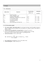
3.2 Connection to power
Note information given on the instrument name
plate (voltage, frequency)!
·
·
·
·
·
·
Electrical connection in conformity with VDE
0100 “Regulations governing heavy-current
installations with rated voltages up to 1000V” or
equivalent national standard.
The
PE protective ground conductor
for supply
power must be connected to the separate U-clamp
terminal in the terminal box of the signal
converter.
Do not cross or loop cables in the terminal box of
the signal converter. Use separate PG or NPT
screwed conduit entries for power and output
cables.
Ensure that the
screw thread of the round cover
on the terminal box is well greased at all times.
Connection to power, VFM 5090(I)
5


