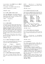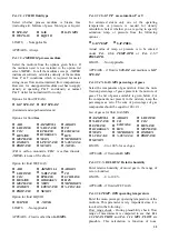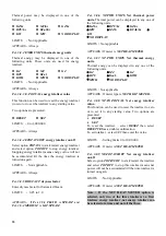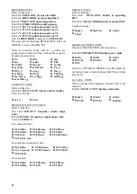
APPEARS - if max. flow
Fct. 1.1.2 MAX.FLOW
is
outside the measuring range of the instrument.
Metering range is computed by sizing the
application as explained in the limits above.
Fct. 4.6 MIN. FLOW
minimum flow rate
Enter the minimum flow rate in the same units as for
MAX. FLOW
above.
MIN. FLOW
should be
within the measuring range for the given primary
data
(3.1.x functions) and application data (3.5.x
functions). If flow rate measured is below min. flow
then an error condition (
LOW FLOW
) will be
generated. Note that this value cannot be zero for
vortex flowmeters.
LIMITS - Limit is calculated from the sizing
calculations from the application data and primary
data. For details of sizing see above paragraph.
APPEARS - if min. flow entered in
Fct. 1.1.3 MIN.
FLOW
is outside the measuring range of
instrument. Metering range is computed by sizing
the application.
Fct. 4.7 0/4mA FLOW
Enter the flow value at which you want current
output at its minimum 0mA (for 0-20 and 0-20/22
=E ranges) or 4mA (for other range options).
LIMITS - Limits are the same as those mentioned
in
Fct. 1.3.4. 0/4mA FLOW.
APPEARS - If value entered in
Fct. 1.3.3 0/4mA
FLOW
lies outside its limits (due to change in flow
range).
Fct. 4.8 20mA FLOW
enter the flow value at which you want current
output at its maximum (20mA). This function and
Fct. 1.3.3.
above define the current output with
respect to flow rate. Note that both the points that
you define are programmable and independent of
min. Flow (
Fct. 1.1.3
) and max. flow (
Fct. 1.1.2.
)
LIMITS - Same as in
Fct. 1.3.4 20 mA FLOW.
APPEARS - if value entered in
Fct. 1.3.4 20mA
FLOW
lies outside its limits (due to change in flow
range).
Fct. 4.9 RANGE F
frequency output range value
The frequency output range value is the frequency
that corresponds to max. flow (
Fct. 1.1.2
). The
other point is always 0 Hz for 0 flow because
frequency output is designed for use with external
totalizers. It is also possible to define range f in
terms of pulses/unit flow .
Example -
Assume max. flow (
Fct. 1.1.2
) = 1000 Kg/hr then
range f = 10000 pulses/hr (at max. flow) and
range f = 10 pulses/Kg are identical. The latter
method is better because it is easy to infer that
totalizer will have a least count of 0.1 Kg ( 10 pulses
per Kg = 1 pulse per 0.1 Kg) and totalizer
programming will be independent of max. flow. The
various options of units for range f are given below.
for volumetric flow -
l
PULSE/hr
l
PULSE/min
l
PULSE/sec
l
PULSE/m3
l
PULS/Litre
l
PULS/ft3
l
PULS/cft
l
PULS/cuft
l
PULS/US.Gal
l
PULS/UK.Gal
for normalized volumetric flow -
l
PULSE/hr
l
PULSE/min
l
PULSE/sec
l
PUL/Norm. m3
l
PULS/Norm.l
l
PULS/sft3
l
PULS/Scft
or mass flow -
l
PULSE/hr
l
PULSE/min
l
PULSE/sec
l
PULS/Kg
l
PULS/t
l
PULS/Lb
LIMITS - 0.0028Hz to 10,000 Hz (Same limits as
in
Fct. 1.4.2 RANGE F.
)
APPEARS - if value entered in
Fct. 1.4.2 RANGE
F
lies outside its limits (due to change in flow range
without subsequently changing
Fct. 1.4.2
and
invalidating its limit).
Fct. 4.10 PULS. WIDTH
pulse width
You can limit the duration of maximum active pulse
width of the frequency output for frequencies less
than or equal to 10 Hz. All options that may appear
are listed below. Only the possible options that are
available (depending on programming of
Fct. 1.4.2
RANGE F
)
to choose are displayed during actual
programming
l
500 mSec.
l
200 mSec
l
100 mSec
l
50 mSec.
l
30 mSec
l
50%
This helps minimize the overheating of totalizer
coils.
LIMITS - Not applicable
APPEARS - if value entered in
Fct. 1.4.2 RANGE
F
is changed such that the existing pulse-width
option is now not valid.
6.1.2. Program function description for AGA
supported software
Fct. 3.8.5 H_VAL.UNITS
Heating value units
May be displayed in one of the following units.
l
KJ / m3
l
MJ / m3
l
GJ / m3
39


