Installation Guide
3-19
Chapter 3. Printer Installation
Printer Connections
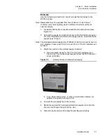
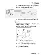
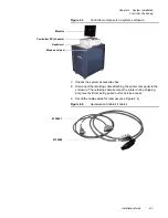
2. Route the cable with the connector at the printer and the cut ends at
the device to be activated (see Figure 3.18).
Figure 3.18
Connector wiring, relay contact cable
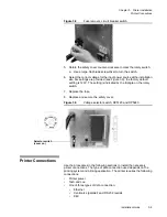
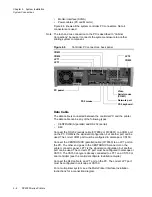
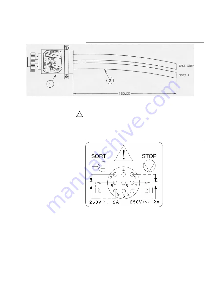
3. Plug the cable into the SORT / STOP connector on the printer back
panel (see Figure 3.19).
!
WARNING
Do not touch the terminals in the cable connector when connecting or
disconnecting the cable. The cable terminals are a high-voltage hazard
when the cable runs from a label base.
Figure 3.19
Sort relay cable connection, printer back panel
4. Power off the device or I/O box being connected.
5. Strip and separate the wires in the cut end of the cable.
6. Connect the brown wire to the terminal for contact 1 (hot).
7. Connect the blue wire to the terminal for contact 2 (neutral).
8. Cap the unused end of the cable.
Summary of Contents for VERSAMARK DP5120
Page 1: ...Versamark DP5000 Series Printers DP5120 DP5122 and DP5240 Installation Guide ...
Page 2: ......
Page 3: ...Versamark DP5000 Series Printers DP5120 DP5240 and DP5122 Installation Guide ...
Page 8: ......
Page 12: ...Contents Figures 4 DP5000 Series Printers ...
Page 14: ...Contents Tables 4 DP5000 Series Printers ...
Page 32: ...2 16 DP5000 Series Printers Chapter 2 Unpacking Printheads ...
Page 52: ...3 20 DP5000 Series Printers Chapter 3 Printer Installation Printer Connections ...
Page 76: ...B 2 DP5000 Series Printers Appendix B Tach and Cue Wiring ...
Page 80: ...C 4 DP5000 Series Printers Appendix C Site Requirements Space Requirements ...
Page 81: ......


