3-16
DP5000 Series Printers
Chapter 3. Printer Installation
Printer Connections
Tach and Cue
The printer requires one of the following types of tach and cue to print:
•
External
•
Internal
•
Custom.
Internal tach and cue are used for testing and for special applications.
This section describes the external tach and cue connection. Internal tach
and cue is produced by software and has no hardware requirements. For
information on configuring a system for custom tach and cue operation,
such as a differential encoder, contact technical support.
Use the following procedure to connect the standard tach and cue
connections shipped with the printer:
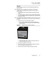
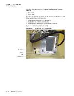
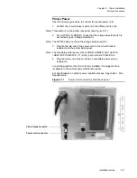
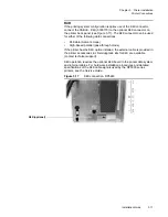
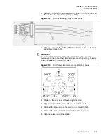
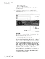
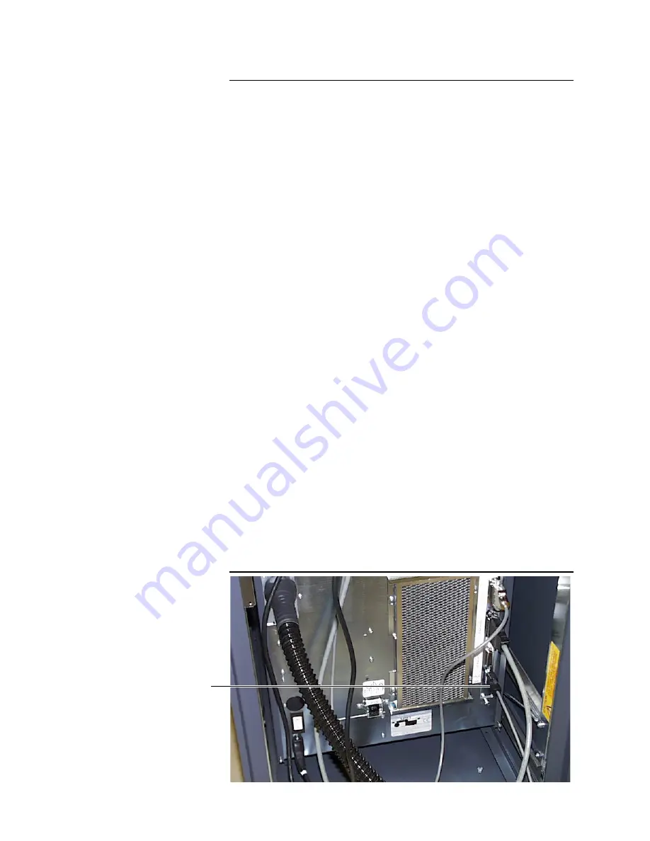
1. Connect one end of the 9-pin CABLE ASSY-TACH/CUE EXT
(0139366) to the TACH / CUE connector on the printer back panel
(see Figure 3.16).
2. Connection to a 200 or 220 system controller requires CABLE,
6240:5120/5240 TACH/CUE. This cable connects the printer to the
tach and cue board in the controller.
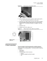
3. Connect the other end of the cable to extension CABLE, 5120/5240
TACH/CUE EXT. 20FT.PKGD (0183205). The extension goes to the
tach encoder and cue sensor.
Note: In a system installation, this cable goes to a T/C port on the system
controller PC.
4. Check that the tach encoder is installed on the document transport
with its friction wheel in contact with a belt or chain that is moving at
the same speed as the substrate (paper).
5. Check that the cue sensor eye is mounted over reflective tape or in
line with the pre-printed cue marks on the web, and located close to
and upstream of the printhead.
Note: See also the vendor documentation shipped with the tach encoder and
cue sensor. Tach and cue wiring is described in “Appendix B, Tach and
Cue Wiring.”
Figure 3.16
Tach and cue connection
Tach and Cue
Summary of Contents for VERSAMARK DP5120
Page 1: ...Versamark DP5000 Series Printers DP5120 DP5122 and DP5240 Installation Guide ...
Page 2: ......
Page 3: ...Versamark DP5000 Series Printers DP5120 DP5240 and DP5122 Installation Guide ...
Page 8: ......
Page 12: ...Contents Figures 4 DP5000 Series Printers ...
Page 14: ...Contents Tables 4 DP5000 Series Printers ...
Page 32: ...2 16 DP5000 Series Printers Chapter 2 Unpacking Printheads ...
Page 52: ...3 20 DP5000 Series Printers Chapter 3 Printer Installation Printer Connections ...
Page 76: ...B 2 DP5000 Series Printers Appendix B Tach and Cue Wiring ...
Page 80: ...C 4 DP5000 Series Printers Appendix C Site Requirements Space Requirements ...
Page 81: ......

