2-6
DP5000 Series Printers
Chapter 2. Unpacking
Printing System
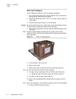
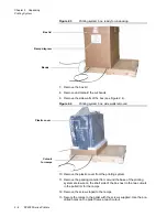
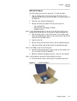
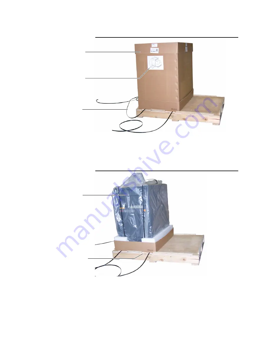
Figure 2.3
Printing system box, ready for unpacking
7. Remove the box lid.
8. Remove and discard the cut bands.
9. Remove the side walls of the box (see Figure 2.4).
Figure 2.4
Printing system box, side walls removed
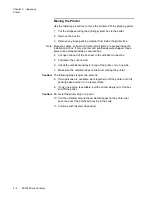
10. Remove the plastic cover from the printing system.
11. Remove the packing material from around the base of the printing
system enclosure on the short side of the box next to the two cutouts
in the pallet rim for the ramps.
12. Remove the screws taped to the ramps.
13. Secure the ramps to the pallet with the screws supplied. Use the pre-
drilled holes on the pallet frame at each cutout.
Ramp diagram
Box lid
Bands
Cutouts
for ramps
Plastic cover
Summary of Contents for VERSAMARK DP5120
Page 1: ...Versamark DP5000 Series Printers DP5120 DP5122 and DP5240 Installation Guide ...
Page 2: ......
Page 3: ...Versamark DP5000 Series Printers DP5120 DP5240 and DP5122 Installation Guide ...
Page 8: ......
Page 12: ...Contents Figures 4 DP5000 Series Printers ...
Page 14: ...Contents Tables 4 DP5000 Series Printers ...
Page 32: ...2 16 DP5000 Series Printers Chapter 2 Unpacking Printheads ...
Page 52: ...3 20 DP5000 Series Printers Chapter 3 Printer Installation Printer Connections ...
Page 76: ...B 2 DP5000 Series Printers Appendix B Tach and Cue Wiring ...
Page 80: ...C 4 DP5000 Series Printers Appendix C Site Requirements Space Requirements ...
Page 81: ......


