3-18
DP5000 Series Printers
Chapter 3. Printer Installation
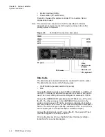
Printer Connections
Sort / Stop
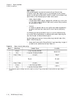
If the printing system requires sort codes sent over the sort relay
connector, a sort relay cable must be connected between the external
device or an I/O box and the SORT / STOP connector on the printer back
panel. Either of the following types of cable can be used:
•
Cable, relay contacts:
The standard CABLE, RELAY CONTACTS (0178910) is 30.0 ft (9.14
m). This cable is part of FRU 0178938 which includes this procedure
as instruction 0178939.
•
Custom:
A customer-supplied cable can be used for specialized applications.
A custom cable can have wires only for the connector pins being
used.
The following procedure describes how to connect the standard cable.
For custom cable specifications, or additional information regarding the
use of sort codes, contact technical support.
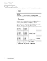
Use the following procedure to connect the relay contacts cable to the
SORT / STOP connector:
1. Select which side (half) of the split cable to use depending on type of
contacts on the external device (see Table 3.2).
Table 3.2
Relay contact cable wiring
Wire #
Wire Color
Contact / Type
Function
1
Brown
1 (hot) / Normally CLOSED
BASE STOP
2
Blue
2 (neutral) / Normally CLOSED
3
Green / Yellow
- (Ground)
Shield
1
4
No pins
Not used
5
6
7
Green / Yellow
- (Ground)
Shield
8
Brown
1 (hot) / Normally OPEN
SORT A
9
Blue
2 (neutral) / Normally OPEN
1.
The green/yellow wires (not shown) are not connected to a contact. They provide partial shock protection when high voltage is
present.
Summary of Contents for VERSAMARK DP5120
Page 1: ...Versamark DP5000 Series Printers DP5120 DP5122 and DP5240 Installation Guide ...
Page 2: ......
Page 3: ...Versamark DP5000 Series Printers DP5120 DP5240 and DP5122 Installation Guide ...
Page 8: ......
Page 12: ...Contents Figures 4 DP5000 Series Printers ...
Page 14: ...Contents Tables 4 DP5000 Series Printers ...
Page 32: ...2 16 DP5000 Series Printers Chapter 2 Unpacking Printheads ...
Page 52: ...3 20 DP5000 Series Printers Chapter 3 Printer Installation Printer Connections ...
Page 76: ...B 2 DP5000 Series Printers Appendix B Tach and Cue Wiring ...
Page 80: ...C 4 DP5000 Series Printers Appendix C Site Requirements Space Requirements ...
Page 81: ......

