


Installation Guide
3-9
Chapter 3. Printer Installation
Printer Connections
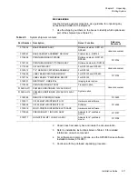
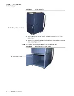
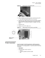
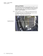
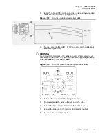
Figure 3.8
Fuse removal, circuit breaker switch
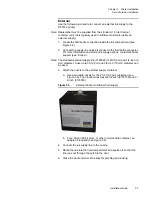
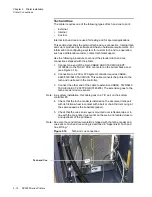
5. Rotate the safety cover counter-clockwise to clear the rotary switch.
a. Use a large, flat-blade screwdriver to turn the switch.
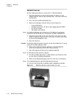
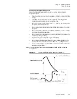
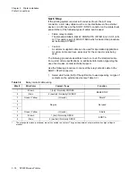
6. Select the correct voltage for the input power source at the installation
site. Six settings are provided (see Figure 3.9); the factory default
setting is 120V. The setting is indicated by the triangle on the rotary
switch.
7. Replace the fuse.
8. Replace and secure the safety cover.
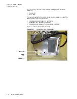
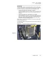
Figure 3.9
Voltage selector switch, DP5120 and DP5240
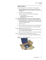
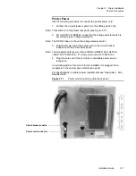
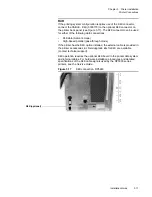
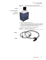
Printer Connections
Use the procedures in the following sections to install the necessary
printer connections. The type of data connection used depends on the
printing system and printing application. The printer requires the following
connections:
•
Printer power
•
Tach and cue
•
One of three types of data connection:
•
Ethernet
•
Centronics (parallel) and RS 232 (serial)
•
K4K.
Selector switch
120V100
V
24
0V
230V
22
0V
200
V
(cover on)
Summary of Contents for VERSAMARK DP5120
Page 1: ...Versamark DP5000 Series Printers DP5120 DP5122 and DP5240 Installation Guide ...
Page 2: ......
Page 3: ...Versamark DP5000 Series Printers DP5120 DP5240 and DP5122 Installation Guide ...
Page 8: ......
Page 12: ...Contents Figures 4 DP5000 Series Printers ...
Page 14: ...Contents Tables 4 DP5000 Series Printers ...
Page 32: ...2 16 DP5000 Series Printers Chapter 2 Unpacking Printheads ...
Page 52: ...3 20 DP5000 Series Printers Chapter 3 Printer Installation Printer Connections ...
Page 76: ...B 2 DP5000 Series Printers Appendix B Tach and Cue Wiring ...
Page 80: ...C 4 DP5000 Series Printers Appendix C Site Requirements Space Requirements ...
Page 81: ......