background image

Scope

Installation Guide

5

Service and Support

Technical equipment support is available 24 hours a day, 7 days a week.

Software and applications support is available 8:00 a.m. to 5:00 p.m. 

EST/EDT, Monday through Friday.

Call for telephone or on-site technical support; to order parts or supplies; 

to request documentation or product information.

Phone

Fax

U.S.A., Canada, and 

worldwide

+1-800-472-4839

+1-937-259-3739

+1-937-259-3808

Europe

+41-21-806-0404

+41-21-806-1920

Asia/Pacific Rim

+65-6744-6400

+65-6744-6700

Japan

+81-03-5621-2220

+81-03-5621-6195

Updated service 

information

http://www.kodakversamark.com

Customer support

[email protected]

Summary of Contents for VERSAMARK DP5120

Page 1: ...Versamark DP5000 Series Printers DP5120 DP5122 and DP5240 Installation Guide ...

Page 2: ......

Page 3: ...Versamark DP5000 Series Printers DP5120 DP5240 and DP5122 Installation Guide ...

Page 4: ...Class A product In a domestic environment this product may cause radio interference in which case the user may be required to take adequate measures Versamark DP5000 Series Printers Printing Systems Installation Guide Kodak 2008 All rights reserved This document contains proprietary information of Eastman Kodak Company or its licensors and is their exclusive property It may not be reproduced witho...

Page 5: ...series printers and the standard enclosure cabinet supplied by Kodak This guide does not describe the Kodak Versamark 5000 Printer Kodak Versamark 5100 Printing System Kodak Versamark 5242 Printing System or Kodak Versamark 5300 Printing System Jetscape software and Mailscape Version 3 96 including the Read Image option are described only as shipped in the dual controller configuration See below I...

Page 6: ...n imminent hazard that will result in serious injury or death This style Refers to Ready Text displayed by the software go Anything you type exactly as it appears whether referenced in text or at a prompt ENTER Special keys on the keyboard such as enter alt and spacebar NEXT Buttons and lights on the printer operator panel Save Software command buttons and sections of dialog boxes such as group bo...

Page 7: ...l for telephone or on site technical support to order parts or supplies to request documentation or product information Phone Fax U S A Canada and worldwide 1 800 472 4839 1 937 259 3739 1 937 259 3808 Europe 41 21 806 0404 41 21 806 1920 Asia Pacific Rim 65 6744 6400 65 6744 6700 Japan 81 03 5621 2220 81 03 5621 6195 Updated service information http www kodakversamark com Customer support custome...

Page 8: ......

Page 9: ...thead 2 13 DH5240 Printhead 2 14 DH5122 Printhead 2 15 Chapter 3 Printer Installation Printer Positioning 3 1 Printer Stand Installation 3 1 Customer Supplied Support 3 3 Fluid Container Installation 3 4 Internal 3 4 Ink Bottle 3 5 Replenisher Bottle 3 6 External 3 7 Voltage Selection 3 8 Printer Connections 3 9 Printer Power 3 11 Ethernet 3 12 RS 232 Serial 3 13 Centronics Parallel 3 14 Control I...

Page 10: ... 2 DH5240 Printhead 5 3 DH5122 Printhead 5 4 Chapter 6 Testing Electronics Tests 6 1 Fluidics Tests 6 2 System Tests 6 3 Printhead Adjustment 6 5 Phase Adjustment 6 5 Adjusting Voltage 6 6 Appendix A Installation Checklists Printer Checklist A 1 Printhead Checklist A 1 Printing System Checklist A 2 Appendix B Tach and Cue Wiring Appendix C Site Requirements Electrical Requirements C 1 Environmenta...

Page 11: ...panel 3 12 Figure 3 13 RS 232 serial connection printer back panel 3 13 Figure 3 14 Parallel data connection printer 3 14 Figure 3 15 Control I O connection printer back panel 3 15 Figure 3 16 Tach and cue connection 3 16 Figure 3 17 K4K connection DP5240 3 17 Figure 3 18 Connector wiring relay contact cable 3 19 Figure 3 19 Sort relay cable connection printer back panel 3 19 Figure 4 1 Cabinet re...

Page 12: ...Contents Figures 4 DP5000 Series Printers ...

Page 13: ...tem shipment contents 2 11 Table 2 6 Printhead models and shipping numbers 2 12 Table 3 1 Fluid part numbers DP5000 series printers 3 4 Table 3 2 Relay contact cable wiring 3 18 Table 5 1 Printhead container contents DH5120 printhead 5 2 Table 5 2 Printhead container contents DH5240 printhead 5 3 Table 5 3 Printhead box contents DH5122 5 4 Table C 1 Electrical requirements C 1 Table C 2 Environmen...

Page 14: ...Contents Tables 4 DP5000 Series Printers ...

Page 15: ...ving components Use two persons to lift the printer box the printing system enclosure or any large component or any box that exceeds 50 lbs 27 kg Lift carefully using the legs and not the back see OSHA standards Electrical Safety Apply the following guidelines when working with any internal component of the printer or around any power source Observe all precautions regarding high voltage Use prope...

Page 16: ... with the fluid Clean up any spill immediately Wear approved protective equipment see OSHA standards Dispose of hazardous material properly see OSHA standards and all local state and Federal regulations that apply Required Tools Before starting the installation check that you have the following required tools and equipment Standard FE took kit 0177490 ESD protection kit 0110094 The following kits ...

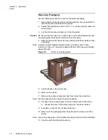
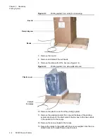
Page 17: ... Printer Printing system Printheads To ensure that you complete all steps of these procedures use the checklists in Appendix A Printer The printer components are shrink wrapped to a shipping pallet see Figure 2 1 Depending on the contents of the product order other boxes may be shipped on the same pallet ...

Page 18: ...set them aside for later unpacking Note A typical printer shipment includes three extra boxes see Printer Inventory Figure 2 1 shows the pallet with the shrink wrap and smaller boxes removed Figure 2 1 Printer on shipping pallet 5 Cut the bands on the printer box 6 Remove the box lid 7 Remove the printer accessories box from inside the printer box Note Set the accessories box aside for later unpac...

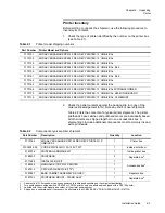
Page 19: ...EY PRINTER 24 UMBILICAL K4K 0170162 KODAK VERSAMARK DP5122 DK GREY PRINTER 12 UMBILICAL 0170163 KODAK VERSAMARK DP5122 DK GREY PRINTER 24 UMBILICAL 0170168 KODAK VERSAMARK DP5120 DK GREY PRINTER 12 UMBILICAL W TRANSFORMER 0170175 KODAK VERSAMARK DP5120 DK GRAY PRINTER 12 UMBILICAL K4K MINUS BOARD 0170176 KODAK VERSAMARK DP5240 DK GREY PRINTER 12 UMBILICAL HI MEMORY Table 2 2 Components typical pri...

Page 20: ...x 4 Cut open the end of the box next to the umbilical connection 5 Fold down the cut box wall 6 Uncoil the umbilical and lay it on top of the printer or to one side 7 Make sure the umbilical does not obstruct moving the printer Caution The following steps require two persons 8 If two persons are available work together to lift the printer out of its packing base and set it on a level surface 9 If ...

Page 21: ...lose as possible to the final location intended for the printing system Note Use a forklift or hand truck to move the pallet 2 Position the pallet where there is 3 ft 1 m of clear working space on all four sides 3 Cut the shrink wrap and remove it from the pallet see Figure 2 2 Caution Do not cut into the boxes Use a box knife or other short bladed tool and cut where pallet contents do not touch t...

Page 22: ... walls removed 10 Remove the plastic cover from the printing system 11 Remove the packing material from around the base of the printing system enclosure on the short side of the box next to the two cutouts in the pallet rim for the ramps 12 Remove the screws taped to the ramps 13 Secure the ramps to the pallet with the screws supplied Use the pre drilled holes on the pallet frame at each cutout Ra...

Page 23: ...safer to pull the cabinet down the ramp rather than to push it down The printer weighs approximately 100 lbs 45 kg and pulling the cabinet down allows you to guide and slow it as it moves down the ramps Caution Do not let the cabinet roll free or tip more than 20 degrees as it moves down the ramps 18 Remove any packaging material from inside the cabinet 19 Remove the umbilical and printhead housin...

Page 24: ... NO MTU 12 UMBILICAL CS150 0170160 KODAK VERSAMARK DP5120 DK GREY SYSTEM NO MTU 24 UMBILICAL JETSCAPE 0170164 KODAK VERSAMARK DP5122 DK GREY SYSTEM NO MTU DUAL CONTROLLER 12 UMBILICAL 0170165 KODAK VERSAMARK DP5122 DK GREY SYSTEM NO MTU DUAL CONTROLLER 24 UMBILICAL 0170166 KODAK VERSAMARK DP5122 DK GREY SYSTEM NO MTU DUAL CONTROLLER 12 UMBILICAL MPI 0170167 KODAK VERSAMARK DP5122 DK GREY SYSTEM NO...

Page 25: ...MBILICAL 1 On pallet 0100238 026 CORD PWR 16AWG 13A 125V 7 5FT 1 Accessories box 0185072 DUAL CONTROLLER PC KIT2 1 Separate box MONITOR 1 Separate box 0188200 PH 2 120 DPI PKD3 2 Separate box 0177489 INSTALLATION KIT 1 Accessories box 0188399 MANUALS KIT DP5122 PRINTING SYSTEM 1 0187412 CATCH PAN SERVICE 1 2 1 0177184 TACH KIT BELT DRIVEN TRANSPORT 1 0175780 CUE ASSY 6 FT W PKG 1 0187887 BASE CABI...

Page 26: ... unpacked when installed see Chapter 4 System Installation 3 Unpack the PC peripherals box it contains the following items Keyboard Mouse PC manuals PC cables 4 Set the PC peripherals aside until ready to begin the system installation 5 Unpack the system accessories box The following contains the system components Manuals set up to six books Cables Power cord kit Installation kit 6 If options or a...

Page 27: ...SEMBLY DK GRAY Printer stand DP5122 0176498 PRINTHEAD MOUNT STAND Rollaround stand DP5120 DP5240 0113754 0187733 PRINTHEAD MOUNT 2 STAND ASSY Rollaround stand for DP5122 0177499 CATCH PAN ASSY For DP5120 and DP5240 Vendor document 0187412 1 2 SERVICE CATCHPAN ASSEMBLY For DP5122 0176499 LABEL BASE PRINTHEAD MOUNT For DP5120 and DP5240 0113754 0187734 LABEL BASE 2 PRINTHEAD MOUNT For DP5122 0182591...

Page 28: ...e general installation guidelines Refer to the documents listed in Table 2 6 for detailed instructions Table 2 6 Printhead models and shipping numbers Part Number Printer Model and Options Installation Documents 0139750 KODAK VERSAMARK DH5120 PRINTHEAD DP5000 series printheads Replacement Instructions 0114252 602 and Packing Instructions 0114253 602 0181000 KODAK VERSAMARK DH5240 PRINTHEAD 0188200...

Page 29: ... should match the printhead serial number on the outer box label Record this number for the installation report 5 Open the inner box Caution Cut the tape carefully using a box knife or other short bladed tool to avoid cutting the printhead capsule inside 6 Remove the printhead capsule carefully to avoid damaging the protruding components catcher flex cable assembly 7 Open the capsule and remove th...

Page 30: ...er on the inner box label This number should match the printhead serial number on the outer box label Record this number for the installation report 5 Open the inner box Caution Cut the tape carefully using a box knife or other short bladed tool to avoid cutting the printhead capsule inside 6 Remove the printhead capsule carefully to avoid damaging the protruding components catcher flex cable asse...

Page 31: ...in the printer or system installation kit 4 Note the serial number on the inner box label This number should match the printhead serial number on the outer box label Record this number for the installation report 5 Open the inner box 6 Remove the top cushion section and remove the printhead capsule 7 Open the printhead capsule and remove the printhead assembly Note Four Phillips screws secure the ...

Page 32: ...2 16 DP5000 Series Printers Chapter 2 Unpacking Printheads ...

Page 33: ...he printer on the rollaround printer stand 1 Position the assembled stand next to the printer shipping pallet 2 Remove the packing material from the pallet to clear the base of the printer all four bottom edges of the printer enclosure 3 Locate the four holes in the top of the stand that correspond to the printer feet Orient the stand with its sliding doors at the front of the printer the operator...

Page 34: ... printer so that all four feet line up with the holes in the stand top 6 Secure the printer to the stand with the four screws provided with the stand see Figure 3 2 Note The screws go up through the stand top into the four feet Figure 3 2 Screw locations printer stand Rubber foot position on stand Screw access to foot ...

Page 35: ...late Do not mount the printhead or route the umbilical lower than 2 ft 61 cm below the printer baseplate Do not mount the printhead more than 0 5 inch 12 7 mm above the substrate printing surface Figure 3 3 diagrams all positioning specifications Do not stretch the umbilical Mount the printer close enough to the printhead that the umbilical reaches without being visibly strained Leave at least 3 i...

Page 36: ... and replenisher fluid shipped in the standard container packaging and installation are the same Table 3 1 lists the most common fluids used in DP5000 series printers Table 3 1 Fluid part numbers DP5000 series printers Fluid Part Number Standard Container Notes 1000 Black Ink 6001000 05 1 5L bladder in carton1 1 Shipped by case or case a case is four 1 5L fluid containers 1006 Black Ink 6001006 05...

Page 37: ...position between the metal supports with the cutouts in the container facing out toward the door Hint Pull up on the bottle neck while sliding it into position 4 Make sure that the flower shaped collar of the bottle is above the metal support arm Caution If the bottle collar is left under the support arm the bottle bladder will collapse inside the container and block the bottom of the ink supply t...

Page 38: ...g out toward the door Hint Pull up on the bottle neck while sliding it into position 4 Make sure that the flower shaped collar of the bottle is above the metal support arm Caution If the bottle collar is left under the support arm the bottle bladder will collapse inside the container and block the bottom of the replenisher supply tube Over time this problem produces high ink concentration 5 When y...

Page 39: ...ntact technical support see Scope Note The standard external supply line 0183648 is 20 ft 6 m and 1 4 inch 6 mm diameter Lines up to 30 ft 9 m and 3 8 inch 10 mm diameter can be used 3 Attach the nozzle to the external supply container a Use a standard nozzle for the 20 0 l 5 3 gal cubitainer see Figure 3 5 The standard nozzles are 1 4 inch 0118739 and 3 8 inch 0118740 Figure 3 5 External 20 liter...

Page 40: ...nter until the correct voltage switch is selected Applying power at the incorrect voltage will damage the printer 1 Locate the circuit breaker switch and confirm that it is in the offline O position see Figure 3 7 2 Locate the voltage selector switch above the circuit breaker switch 3 Loosen the two screws securing the safety cover to the switch see Figure 3 7 Figure 3 7 Voltage selector switch co...

Page 41: ...20V The setting is indicated by the triangle on the rotary switch 7 Replace the fuse 8 Replace and secure the safety cover Figure 3 9 Voltage selector switch DP5120 and DP5240 Printer Connections Use the procedures in the following sections to install the necessary printer connections The type of data connection used depends on the printing system and printing application The printer requires the ...

Page 42: ...rfaces Control I O Sort Stop The cables required for the printer connections are provided in one of the following kits shipped with the printer HARDWARE AND CABLE KIT 0175833 SHIPPING KIT PRINTER 0178223 HARDWARE CABLE KIT DARK GRAY 0187976 Figure 3 10 shows the printer connectors Figure 3 10 Connectors printer back panel K4K Power Sort Stop Centronics ...

Page 43: ...he voltage selector switch 3 Plug the female end of the power cord to the circuit breaker receptacle on the printer back panel Note The standard printer power cord is CORD JUMPER ACC UL CSA HAR M F 10A 250V 8 2 2 5m part number 0100238 102 4 Plug the male end of the cord into a compatible power source receptacle In a printing system this cord is factory installed it is plugged into a receptacle in...

Page 44: ...M 6FT 0100378 203 CBL COAX THINET BNCM BNCM 30FT 0100378 207 Ethernet operation requires special printer software and internal hardware Besides the transceiver that provides the BNCM connector 0178559 an internal cables connect the transceiver to the DS Main board 0178981 and 0178530 All the necessary components are available in the 5000 SERIES ENET KIT 0181331 For specifications of the Thinet con...

Page 45: ...the printer back panel see Figure 3 13 This cable goes to a COM port on the system controller host PC see Controller Connections in Chapter 4 System Installation Note CABLE SERIAL PC 5120 5240 0139601 is the standard serial cable For detailed specifications of the RS 232 cable signals used by the DP5000 series printers see the Service Guide Figure 3 13 RS 232 serial connection printer back panel R...

Page 46: ...or on the printer back panel see Figure 3 14 This cable goes to the parallel printer port on the system controller host PC see Controller Connections in Chapter 4 System Installation Note CABLE PARALLEL 6 FOOT 0139268 is the standard parallel cable For detailed specifications of the CENTRONICS cable signals used by the DP5000 series printers see the Service Guide Figure 3 14 Parallel data connecti...

Page 47: ...system controller I O board or to an I O box using the same 40 pin connector CABLE ASSY SIGS SORT CODE ADAPT 24 0178602 This cable adapts the control I O connector to the cable used for the SORT STOP relay contact closure cable This cable typically goes to a stacker sorter or other inline device activated by sort codes embedded in the image data being printed Either cable is connected to the CONTR...

Page 48: ...ure 3 16 2 Connection to a 200 or 220 system controller requires CABLE 6240 5120 5240 TACH CUE This cable connects the printer to the tach and cue board in the controller 3 Connect the other end of the cable to extension CABLE 5120 5240 TACH CUE EXT 20FT PKGD 0183205 The extension goes to the tach encoder and cue sensor Note In a system installation this cable goes to a T C port on the system cont...

Page 49: ...ions K4K data Admark mode High Speed parallel pass through mode If the printer has the K4K option installed the external cable is provided in the printer accessories kit Field upgrade kits for K4K are available contact technical support K4K operation requires the optional K4K board in the printer data system and internal cables For hardware installation procedures and detailed specifications of th...

Page 50: ...ctor pins being used The following procedure describes how to connect the standard cable For custom cable specifications or additional information regarding the use of sort codes contact technical support Use the following procedure to connect the relay contacts cable to the SORT STOP connector 1 Select which side half of the split cable to use depending on type of contacts on the external device ...

Page 51: ...igure 3 19 WARNING Do not touch the terminals in the cable connector when connecting or disconnecting the cable The cable terminals are a high voltage hazard when the cable runs from a label base Figure 3 19 Sort relay cable connection printer back panel 4 Power off the device or I O box being connected 5 Strip and separate the wires in the cut end of the cable 6 Connect the brown wire to the term...

Page 52: ...3 20 DP5000 Series Printers Chapter 3 Printer Installation Printer Connections ...

Page 53: ...ppendix A Enclosure Positioning Use the following procedure to position the system enclosure 1 Check that the umbilical is safely coiled inside the cabinet and that all packing material is clear of the casters If the umbilical was uncoiled coil it safely inside the cabinet see Figure 4 1 Figure 4 1 Cabinet ready for positioning 2 Unlock the enclosure casters The casters should have been locked aft...

Page 54: ... the controller components on top of the system enclosure 1 When the cabinet is properly positioned check that the casters are locked to ensure that the cabinet does not roll while components are being placed on top of it 2 Check that all boxes were brought from the location where the shipping pallet was unpacked 3 Unpack the controller PC and place the processor chassis on top of the enclosure 4 ...

Page 55: ...ox 8 Disconnect the retaining cable attaching the printer rear panel to the enclosure The retaining cable secures the printer during shipping but prevents it from being pulled out for service access 9 Set all the cables aside for later use see Figure 4 4 Figure 4 4 Hardware and cable kit cables Controller PC chassis Monitor Keyboard Mouse and pad 0139601 0139268 ...

Page 56: ... wiring is detailed in Appendix B Apply the following general guidelines to making system connections For detailed information on the interfaces and connectors see the Service Guide Cable tie and bundle all cables that pass through the opening in the top of the cabinet Route the umbilical cabinet power cord tach and cue and other external cables through the left side of the printer cabinet rear pa...

Page 57: ...rnal tach and cue CABLE ASSY TACH CUE EXT 0139366 between the Tach encoder Cue sensor cabling and the TACH CUE connector on the rear panel of the printer The standard external tach and cue cable is included in the installation kit This cable can be used to connect a printer directly to its tach and cue source Other cables of different lengths are available including CABLE ASSY SHLD 9DM 9DF 10FT 01...

Page 58: ...rt on the PC COM2 is the standard configuration but another port can be used The correct COM port must be configured in Jetscape or CS150 Connect the CENTRONICS parallel cable 0178550 to an LPT port on the PC The other end goes to the CENTRONICS connector on the printer connector panel LPT1 is the standard configuration but another port can be used The correct LPT port must be configured in Jetsca...

Page 59: ...ble into the PS mouse connector on the PC back panel see Figure 4 7 Note On older Jetscape controllers GlidePoint was plugged into COM1 Figure 4 7 Controller data keyboard and mouse cables Monitor Interface Plug the SVGA cable permanently affixed to the monitor into the VIDEO connector on the PC back panel see Figure 4 8 Secure the connector by tightening the set screws until snug do not over tigh...

Page 60: ...he power receptacles on the PC and monitor see Figure 4 9 Route the cables down into the cabinet through the cutout in the top and plug the male ends of the cables into 110V receptacles in the front of the power distribution panel inside the cabinet Figure 4 9 PC and monitor power cables Installing Software Install the CS150 system controller software on the controller PC The installation of the s...

Page 61: ...e information in this chapter supplements the instructions shipped with a replacement printhead For detailed printhead installation and removal procedures consult the documents shipped with each printhead Caution Always take precautions against electro static discharge when handling a printhead To ensure that you complete all steps of the procedures complete the Printhead Checklist in Appendix A ...

Page 62: ...fore removing the printhead from its capsule The capsule is secured with four Phillips screws Handle the capsule carefully to avoid damaging the NV RAM board and its attached cable The DH5120 printhead connections are inlet line outlet line NV RAM board connector and two screws slotted Note the printhead serial number for the installation report After replacing the covers continue with the procedu...

Page 63: ...ns before removing the printhead from its capsule The capsule is secured with four Phillips screws Handle the capsule carefully The DH5240 printhead connections are inlet line outlet line adapter board connector catcher line and two latches Note the printhead and eyelid serial numbers for the installation report After replacing the covers continue with the procedures in Chapter 6 Testing Figure 5 ...

Page 64: ...he installation procedure in the printhead Replacement Instructions 0114252 before removing the printhead from inner printhead box Handle the box carefully to avoid damaging the printhead The box is secured with four Phillips screws Note the printhead serial number for the installation report After replacing the covers the position of the cover screw can vary slightly continue with the procedures ...

Page 65: ...n power switch on the power distribution panel For a printer check that the line switch on the back panel is in the online position 2 While holding the OPEN EYELID button press the PRINTER ON button 3 Continue to hold the OPEN EYELID button until all lights on the front panel are illuminated 4 Release the OPEN EYELID button 5 On a printing system turn on all the components 6 Check for error messag...

Page 66: ...er online help and Getting Started Guide 4 Select Mode Maintenance 5 Choose Select State Table Type Circulate and then OK 6 On the Maintenance screen select the Printer to State button 7 Enter 2 in the dialog box that opens and select OK Note Wait approximately 3 minutes for the ink tank to fill When the fill cycle is complete state 2 has been reached 8 Enter 6 in the dialog box to complete test N...

Page 67: ...t print check for tach and cue see System Tests If print quality is poor adjust the phase and voltage see Printhead Adjustment b If the test pattern print quality is acceptable the system is opera tional and the installation is complete Continue with the installa tion report System Tests Use the following procedure to test the operation of the printing system 1 Turn on the printer 2 Press PRINTER ...

Page 68: ... the maximum values If the existing values exceed the new maximum values the existing values are truncated to the new maximum values 8 If no known good values are available use the following values as a guideline for test printing Image length 7 0 Substrate length Per application Printhead height 0 2 Transport direction Per application Piece orientation 180 Cue distance Per application Cue delay 0...

Page 69: ...ress TEST PRINT again 12 Check the test patterns 13 If test patterns print check the print quality If the print quality is acceptable the system is operational and the installation is complete Continue with the installation report 14 If print quality is not acceptable adjust the printhead phase and voltage see Printhead Adjustment If test patterns do not print run full diagnostics starting with th...

Page 70: ...e phase window that produces the best print quality Apply the following guidelines to phase adjustment A voltage setting that is out of the print window range can affect the phase window A phase setting that is near the edge of the phase window range can affect the print window Print speed may also affect the print window Use 400 fpm 122 mpm as the standard print speed for print window evaluation ...

Page 71: ... 58 12 If the resulting value exceeds 55 subtract it from the high end setting For the example above 48 10 58 12 10 2 13 Note the resulting value it is the mid range phase setting 14 Select Mode Settings Printer Setup and enter the mid range value 15 Press APPLY to save this setting Adjusting Voltage Use the following procedure to determine the print window and the mid range value to be used as th...

Page 72: ... the low end setting of the print window causes increased dark defects As the voltage drops further streakers appear 7 Select Mode Settings Printer Setup and enter a value 10 volts above the low end setting 8 Press APPLY to save this setting 9 Print another test pattern to verify the phase and voltage settings If print quality is unsatisfactory repeat both procedures ...

Page 73: ...d mount the printhead housing Connect the external printer cables power tach and cue Select the input voltage not required for DP5122 Power up and test the printer electronics Continue with the printhead checklist Printhead Checklist Unpack the printhead Remove the printhead covers Install the printhead assembly Install the eyelid assembly Install lockout switch actuator tool Test the printer flui...

Page 74: ...ition the computer components Connect the internal system cables Connect the printer cables Select the input voltage not required for DP5122 printer Install the tach encoder and cue sensor assemblies Connect the external system cables Power up and test the system controller Complete the Printhead Checklist procedures Install the multi printer interface option if required Repeat the installation pr...

Page 75: ...gure B 1 as a guideline for wiring the standard tach encoder and cue sensor Figure B 1 Tach and cue wiring DP5000 series printers Tach Encoder Cue Sensor INVERTED CUE SIG GRN 5 VDC RED TACH IN BRN TACH IN BRN GND BLK 3 7 8 5 9 6 CUE IN WHITE 12 VDC RED GRD BLACK ...

Page 76: ...B 2 DP5000 Series Printers Appendix B Tach and Cue Wiring ...

Page 77: ... of all three DP5000 series printers and the dual controller printing system Table C 1 Electrical requirements Product Voltage VAC 1 Current Amps Cycles Hertz VA DP5120 printer 100 120 200 220 230 240 6 10 Single phase Switchable 6 3 4 4 4 4 4 50 60 630 480 800 920 960 DP5240 printer DP5122 printer 100 120 6 10 Single phase 4 A System with CS150 controller 100 120 200 220 230 240 6 10 Single phase...

Page 78: ...s1 Length2 Width3 Height4 Weight5 Printer enclosure 23 4 59 5 17 7 44 9 18 7 47 5 110 0 49 8 17 9 45 7 Printer stand 23 5 60 18 0 45 7 19 0 49 3 20 0 9 1 System enclosure 32 4 82 3 22 1 56 2 35 88 91 1 45 0 20 4 DH5120 printhead 5 13 13 02 1 98 5 03 11 79 29 95 2 5 1 1 DH5240 printhead 4 81 12 22 2 39 6 09 11 94 30 33 DH5122 printhead 5 18 13 16 3 90 9 91 5 1 2 3 12 ft Umbilical 144 0 365 8 1 3 3 ...

Page 79: ...Installation Guide C 3 Appendix C Site Requirements Space Requirements Figure C 1 DH5122 printhead dimensions ...

Page 80: ...C 4 DP5000 Series Printers Appendix C Site Requirements Space Requirements ...

Page 81: ......

Page 82: ...stman Kodak Company 3000 Research Boulevard Dayton OH 45420 U S A Kodak 2008 TM Kodak Versamark To learn more about solutions from Kodak visit graphics kodak com Subject to technical change without notice ...

Reviews: