


Section 7
Hydraulic System
20428738
11-2005/Rev 01
7-16
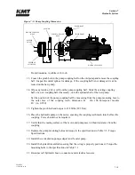
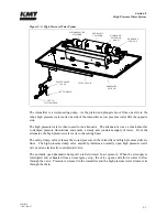
Figure 7-10: Motor Coupling Half
5.
Apply Loctite 222 to the bolts and attach a new motor coupling half to the motor shaft.
Torque to the specifications in Table 7-3.
6.
Place the flexible coupling on the motor coupling half. Follow Step 12 and 14 in the
previous procedure to determine if the coupling half on the hydraulic pump is in the
proper position. If necessary, adjust the position of the pump coupling half.
7.
Place the hydraulic pump on the motor, ensuring the coupling teeth mesh into the flexible
coupling. Force should not be required.
8.
Verify that the mating surfaces of the motor and pump meet without resistance from the
coupling.
9.
Replace the pump mounting bolts and torque to the specifications in Table 7-3.
10.
Position the motor and hydraulic pump in the frame. Attach the motor to the vibration
isolation mounts.
11.
Install the flexible electrical cable on the junction box and replace the electrical leads.
12.
Complete Steps 19-24 in the previous procedure.
FLEXIBLE
COUPLING
MOTOR
COUPLING HALF
Summary of Contents for STREAMLINE SL-V SRP 100
Page 23: ......
Page 25: ......
Page 174: ...Section 12 Parts List 20428786 2 2008 Rev 05 12 5 Figure 12 1 SL V SRP 100 Intensifier Unit ...
Page 176: ...Section 12 Parts List 20428786 2 2008 Rev 05 12 7 Figure 12 2 Intensifier Assembly ...
Page 184: ...Section 12 Parts List 20428786 2 2008 Rev 05 12 15 Figure 12 7 High Pressure Piping ...
Page 188: ...Section 12 Parts List 20428786 2 2008 Rev 05 12 19 Figure 12 9 Hydraulic Power Package ...
Page 190: ...Section 12 Parts List 20428786 2 2008 Rev 05 12 21 Figure 12 10 Motor Pump Assembly ...
Page 192: ...Section 12 Parts List 20428786 2 2008 Rev 05 12 23 Figure 12 11 Hydraulic Manifold Assembly ...
Page 194: ...Section 12 Parts List 20428786 2 2008 Rev 05 12 25 Figure 12 12 Hydraulic Hose Connections ...
Page 196: ...Section 12 Parts List 20428786 2 2008 Rev 05 12 27 Figure 12 13 Reservoir Assembly ...
Page 199: ...Section 12 Parts List 20428786 2 2008 Rev 05 12 30 Figure 12 14 Bulkhead Pipe Assembly ...
Page 201: ...Section 12 Parts List 20428786 2 2008 Rev 05 12 32 Figure 12 15 Cover Assembly ...
Page 205: ...Section 12 Parts List 20428786 2 2008 Rev 05 12 36 Figure 12 17 Electrical Assembly 230 50 60 ...
Page 223: ...Section 12 Parts List 20428786 2 2008 Rev 05 12 54 Figure 12 25 High Pressure Transducer ...
Page 224: ......
Page 225: ......
Page 226: ......
Page 227: ......
Page 228: ......
Page 229: ......
Page 230: ......
Page 231: ......
Page 232: ......
Page 233: ......
Page 234: ......
Page 235: ......
Page 236: ......
Page 237: ......
Page 238: ......
Page 239: ......


