


Section 7
Hydraulic System
20428738
11-2005/Rev 01
7-3
The main system relief valve provides system protection by monitoring the oil pressure entering
the manifold. If the hydraulic pressure exceeds 3,400 psi (235 bar), the valve opens to limit the
pressure. The valve is factory calibrated and is not serviceable. A drain line from the valve
prevents oil from collecting behind the relief valve to ensure a constant pressure under all
operating conditions.
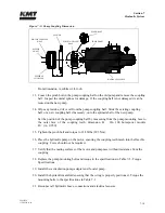
The hydraulic system operates at high or low pressure settings up to the maximum flow capacity
of the hydraulic pump. The high and low limit compensators mounted on the pump regulate the
flow of hydraulic fluid to maintain constant operating pressures. Operating pressures are set and
adjusted at the high and low pressure control valves on the manifold.
If the machine is equipped with proportional pressure control, low pressure is adjusted at the
manifold, and the high pressure setting is made from the control panel or a remote console.
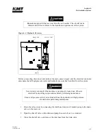
The high and low limit compensators regulate the flow of hydraulic fluid to the
system by controlling the angle of the swashplate. If the oil is not properly
maintained, the compensators can become blocked with debris. As a result, pump
control will be lost and you will not be able to create hydraulic oil pressure.
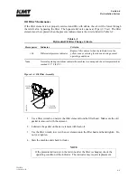
The normally closed, two pressure solenoid valve is controlled by the operator’s selection of high
or low pressure. The valve is closed while operating in high pressure and is open during low
pressure operation. A light on the solenoid connector indicates low pressure operation.
At startup, hydraulic pressure is automatically switched to low, limiting torque demand. After 5-
60 seconds, depending on the interval selected by the operator, hydraulic pressure automatically
returns to the previously selected pressure setting.
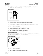
A reference gauge on the top of the manifold displays hydraulic pressure to the intensifiers.
When the intensifier shifts, it is normal for the pressure to quickly fall and then rise again.
The 4-way directional control valve directs pressurized oil to one end the hydraulic cylinder and
returns fluid to the reservoir from the opposite end, causing the intensifier to stroke. The
movement is controlled hydraulically by a pilot valve that is electronically operated by two
solenoids, energized by the PLC. Indicators light up as each solenoid is energized.
The directional control valve sends flow to the hydraulic cylinder in one direction until the
hydraulic piston activates the proximity switch at the end of the stroke. The activated switch
sends a signal to the PLC to reverse the direction of flow. The piston then moves in the opposite
direction until it activates the proximity switch at the opposite end of the stroke.
Summary of Contents for STREAMLINE SL-V SRP 100
Page 23: ......
Page 25: ......
Page 174: ...Section 12 Parts List 20428786 2 2008 Rev 05 12 5 Figure 12 1 SL V SRP 100 Intensifier Unit ...
Page 176: ...Section 12 Parts List 20428786 2 2008 Rev 05 12 7 Figure 12 2 Intensifier Assembly ...
Page 184: ...Section 12 Parts List 20428786 2 2008 Rev 05 12 15 Figure 12 7 High Pressure Piping ...
Page 188: ...Section 12 Parts List 20428786 2 2008 Rev 05 12 19 Figure 12 9 Hydraulic Power Package ...
Page 190: ...Section 12 Parts List 20428786 2 2008 Rev 05 12 21 Figure 12 10 Motor Pump Assembly ...
Page 192: ...Section 12 Parts List 20428786 2 2008 Rev 05 12 23 Figure 12 11 Hydraulic Manifold Assembly ...
Page 194: ...Section 12 Parts List 20428786 2 2008 Rev 05 12 25 Figure 12 12 Hydraulic Hose Connections ...
Page 196: ...Section 12 Parts List 20428786 2 2008 Rev 05 12 27 Figure 12 13 Reservoir Assembly ...
Page 199: ...Section 12 Parts List 20428786 2 2008 Rev 05 12 30 Figure 12 14 Bulkhead Pipe Assembly ...
Page 201: ...Section 12 Parts List 20428786 2 2008 Rev 05 12 32 Figure 12 15 Cover Assembly ...
Page 205: ...Section 12 Parts List 20428786 2 2008 Rev 05 12 36 Figure 12 17 Electrical Assembly 230 50 60 ...
Page 223: ...Section 12 Parts List 20428786 2 2008 Rev 05 12 54 Figure 12 25 High Pressure Transducer ...
Page 224: ......
Page 225: ......
Page 226: ......
Page 227: ......
Page 228: ......
Page 229: ......
Page 230: ......
Page 231: ......
Page 232: ......
Page 233: ......
Page 234: ......
Page 235: ......
Page 236: ......
Page 237: ......
Page 238: ......
Page 239: ......


