


Section 9
High Pressure Water System
20428754
7-2007/Rev 03
9-28
2.
Disconnect the high and low pressure water piping from both ends of the intensifier,
following the procedure, High and Low Pressure Water Piping.
3.
Remove the high pressure cylinder assembly on each end of the intensifier, following the
procedure, High Pressure Cylinder Assembly Removal.
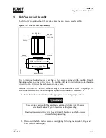
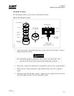
Figure 9-20: Hydraulic Piston Removal
4.
Remove both of the proximity switches to prevent interference and to allow the hydraulic
oil to drain back to the reservoir, minimizing oil spillage. It will take approximately five
minutes for the oil to drain.
5.
Remove the retaining ring, bushing retainer flange and the hydraulic cartridge seal from
both hydraulic cylinder heads. It is not necessary to remove the plunger.
6.
Loosen and remove the socket head screws in one of the hydraulic cylinder heads.
7.
Remove the hydraulic cylinder head with the o-ring and backup ring. The mounting flat
for the proximity switch provides a small lip for loosening the cylinder head.
8.
Grasp the plunger firmly and pull the piston out of the hydraulic cylinder.
HYDRAULIC
CARTRIDGE SEAL
SOCKET HEAD
SCREW
HYDRAULIC CYLINDER
HEAD
O-RING
BACKUP RING
O-RING SPACER
HYDRAULIC
CYLINDER
PROXIMITY SWITCHES
BUSHING
RETAINER
FLANGE
RETAINING
RING
HYDRAULIC PISTON
PLUNGER
0
511
954
0
Summary of Contents for STREAMLINE SL-V SRP 100
Page 23: ......
Page 25: ......
Page 174: ...Section 12 Parts List 20428786 2 2008 Rev 05 12 5 Figure 12 1 SL V SRP 100 Intensifier Unit ...
Page 176: ...Section 12 Parts List 20428786 2 2008 Rev 05 12 7 Figure 12 2 Intensifier Assembly ...
Page 184: ...Section 12 Parts List 20428786 2 2008 Rev 05 12 15 Figure 12 7 High Pressure Piping ...
Page 188: ...Section 12 Parts List 20428786 2 2008 Rev 05 12 19 Figure 12 9 Hydraulic Power Package ...
Page 190: ...Section 12 Parts List 20428786 2 2008 Rev 05 12 21 Figure 12 10 Motor Pump Assembly ...
Page 192: ...Section 12 Parts List 20428786 2 2008 Rev 05 12 23 Figure 12 11 Hydraulic Manifold Assembly ...
Page 194: ...Section 12 Parts List 20428786 2 2008 Rev 05 12 25 Figure 12 12 Hydraulic Hose Connections ...
Page 196: ...Section 12 Parts List 20428786 2 2008 Rev 05 12 27 Figure 12 13 Reservoir Assembly ...
Page 199: ...Section 12 Parts List 20428786 2 2008 Rev 05 12 30 Figure 12 14 Bulkhead Pipe Assembly ...
Page 201: ...Section 12 Parts List 20428786 2 2008 Rev 05 12 32 Figure 12 15 Cover Assembly ...
Page 205: ...Section 12 Parts List 20428786 2 2008 Rev 05 12 36 Figure 12 17 Electrical Assembly 230 50 60 ...
Page 223: ...Section 12 Parts List 20428786 2 2008 Rev 05 12 54 Figure 12 25 High Pressure Transducer ...
Page 224: ......
Page 225: ......
Page 226: ......
Page 227: ......
Page 228: ......
Page 229: ......
Page 230: ......
Page 231: ......
Page 232: ......
Page 233: ......
Page 234: ......
Page 235: ......
Page 236: ......
Page 237: ......
Page 238: ......
Page 239: ......


