


Section 2
Installation
20428689
10-2007/Rev 04
2-7
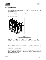
2.6
Flow Requirements
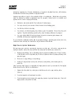
Figure 2-4, Pressure Drop Values, illustrates the pressure drop for four different pipe sizes. The
graph can be used to calculate the minimum source water pressure.
1.
Enter the graph at the required GPM and note the pressure drop figures for the different
pipe sizes.
2.
Multiply the pressure drop (PSI/FT) by the length in feet of each pipe size used from the
water source to the intensifier. Add the values together for a total pressure drop value.
3.
Add 30 to the total pressure drop to determine the minimum flowing, source water
pressure required to provide adequate supply to the intensifier.
Cutting water and cooling water capacity should be calculated separately. Note that the cutting
water requirements represent instantaneous, not average, demand.
The machine will not start if
the inlet cutting water pressure drops below 30 psi (2 bar).
Figure 2-4: Pressure Drop Values
Pipe Sizing
0
0.05
0.1
0.15
0.2
0.25
0.3
0.35
0.4
0.45
0 1 2 3 4 5 6 7 8 9 10 11 12 13 14 15 16 17 18 19 20
Required GPM
P
res
su
re d
r
o
p
(
P
S
I/
F
T
)
1/2" ID
3/4" ID
1" ID
1-1/4" ID
Summary of Contents for STREAMLINE SL-V SRP 100
Page 23: ......
Page 25: ......
Page 174: ...Section 12 Parts List 20428786 2 2008 Rev 05 12 5 Figure 12 1 SL V SRP 100 Intensifier Unit ...
Page 176: ...Section 12 Parts List 20428786 2 2008 Rev 05 12 7 Figure 12 2 Intensifier Assembly ...
Page 184: ...Section 12 Parts List 20428786 2 2008 Rev 05 12 15 Figure 12 7 High Pressure Piping ...
Page 188: ...Section 12 Parts List 20428786 2 2008 Rev 05 12 19 Figure 12 9 Hydraulic Power Package ...
Page 190: ...Section 12 Parts List 20428786 2 2008 Rev 05 12 21 Figure 12 10 Motor Pump Assembly ...
Page 192: ...Section 12 Parts List 20428786 2 2008 Rev 05 12 23 Figure 12 11 Hydraulic Manifold Assembly ...
Page 194: ...Section 12 Parts List 20428786 2 2008 Rev 05 12 25 Figure 12 12 Hydraulic Hose Connections ...
Page 196: ...Section 12 Parts List 20428786 2 2008 Rev 05 12 27 Figure 12 13 Reservoir Assembly ...
Page 199: ...Section 12 Parts List 20428786 2 2008 Rev 05 12 30 Figure 12 14 Bulkhead Pipe Assembly ...
Page 201: ...Section 12 Parts List 20428786 2 2008 Rev 05 12 32 Figure 12 15 Cover Assembly ...
Page 205: ...Section 12 Parts List 20428786 2 2008 Rev 05 12 36 Figure 12 17 Electrical Assembly 230 50 60 ...
Page 223: ...Section 12 Parts List 20428786 2 2008 Rev 05 12 54 Figure 12 25 High Pressure Transducer ...
Page 224: ......
Page 225: ......
Page 226: ......
Page 227: ......
Page 228: ......
Page 229: ......
Page 230: ......
Page 231: ......
Page 232: ......
Page 233: ......
Page 234: ......
Page 235: ......
Page 236: ......
Page 237: ......
Page 238: ......
Page 239: ......


