


Section 7
Hydraulic System
20428738
11-2005/Rev 01
7-7
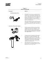
1.
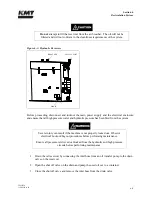
Remove the bolts attaching the motor vibration mounts to the frame base plate.
2.
Use wooden blocks to support the hydraulic pump and manifold assembly. Leave all hose
connections intact.
NOTE
A forklift can also be used by trained, experienced personnel to support the pump
and manifold assembly.
3.
Remove the bolts attaching the hydraulic pump to the electric motor.
4.
Slide the motor away from the pump and manifold assembly to expose the flexible
coupling.
NOTE
If additional clearance is required to separate the motor and pump, the electrical
panel can be removed from the end of the frame. Remove the hex nuts from the
studs holding the electrical panel. Move the panel 4-8 inches away from the frame.
It should not be necessary to disconnect the motor lead wires. However, the wire
ties holding the electrical control harness to the top pan will need to be removed in
order to move the electrical panel.
5.
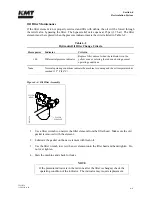
Remove the failed flexible coupling.
6.
Wipe any residue, dirt or oil from the coupling halves on both the motor shaft, and the
pump shaft. Avoid damaging the shaft seal on the pump.
NOTE
Additional clearance and access to the motor and pump coupling can be achieved
by moving the pump and manifold assembly to the right. The pump suction hose
will limit movement to approximately one inch. It should not be necessary to
disconnect any hydraulic hoses.
7.
Inspect the metal splines on the coupling halves for damage. If damage is detected,
replace the coupling half.
8.
Inspect the shaft cavity of the hydraulic pump for the presence of hydraulic oil or evidence
of hydraulic leaks. If a hydraulic leak is detected, the shaft seal must be replaced.
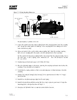
9.
Install the new flexible coupling over the coupling half on the motor shaft, aligning the
splines, and push the flexible coupling on as far as it will go. The internal ring or snap
ring keeps the coupling centered between the motor and pump shafts.
Summary of Contents for STREAMLINE SL-V SRP 100
Page 23: ......
Page 25: ......
Page 174: ...Section 12 Parts List 20428786 2 2008 Rev 05 12 5 Figure 12 1 SL V SRP 100 Intensifier Unit ...
Page 176: ...Section 12 Parts List 20428786 2 2008 Rev 05 12 7 Figure 12 2 Intensifier Assembly ...
Page 184: ...Section 12 Parts List 20428786 2 2008 Rev 05 12 15 Figure 12 7 High Pressure Piping ...
Page 188: ...Section 12 Parts List 20428786 2 2008 Rev 05 12 19 Figure 12 9 Hydraulic Power Package ...
Page 190: ...Section 12 Parts List 20428786 2 2008 Rev 05 12 21 Figure 12 10 Motor Pump Assembly ...
Page 192: ...Section 12 Parts List 20428786 2 2008 Rev 05 12 23 Figure 12 11 Hydraulic Manifold Assembly ...
Page 194: ...Section 12 Parts List 20428786 2 2008 Rev 05 12 25 Figure 12 12 Hydraulic Hose Connections ...
Page 196: ...Section 12 Parts List 20428786 2 2008 Rev 05 12 27 Figure 12 13 Reservoir Assembly ...
Page 199: ...Section 12 Parts List 20428786 2 2008 Rev 05 12 30 Figure 12 14 Bulkhead Pipe Assembly ...
Page 201: ...Section 12 Parts List 20428786 2 2008 Rev 05 12 32 Figure 12 15 Cover Assembly ...
Page 205: ...Section 12 Parts List 20428786 2 2008 Rev 05 12 36 Figure 12 17 Electrical Assembly 230 50 60 ...
Page 223: ...Section 12 Parts List 20428786 2 2008 Rev 05 12 54 Figure 12 25 High Pressure Transducer ...
Page 224: ......
Page 225: ......
Page 226: ......
Page 227: ......
Page 228: ......
Page 229: ......
Page 230: ......
Page 231: ......
Page 232: ......
Page 233: ......
Page 234: ......
Page 235: ......
Page 236: ......
Page 237: ......
Page 238: ......
Page 239: ......


