


Section 7
Hydraulic System
20428738
11-2005/Rev 01
7-11
19.
Open the high pressure water control valve, allowing water to flow. Set the desired high
operating pressure by adjusting the high pressure control valve.
If the machine is equipped with proportional pressure control, select the high operating
pressure on the Pressure Control Screen.
20.
While the machine is running and high pressure water is flowing, select low pressure
operating mode. Set the desired low operating pressure by adjusting the low pressure
control valve.
Hydraulic Pump or Electric Motor Replacement
The following procedures are used to replace the hydraulic pump or the electric motor.
Hydraulic Pump Replacement
1.
Turn the machine off and observe the appropriate Lockout/Tagout procedures.
Severe injury can result if the machine is not properly locked out. Observe
electrical Lockout/Tagout procedures before proceeding.
Ensure all pressure is relieved or blocked from the hydraulic and high pressure
circuits before proceeding.
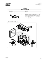
2.
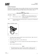
Loosen the hold down screws on the proximity switches to allow the hydraulic oil in the
cylinders and hoses to drain back to the reservoir. It will take approximately five minutes
for the oil to drain.
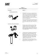
3.
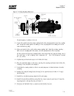
Drain the oil reservoir by connecting the inlet hose from an oil transfer pump to the drain
valve on the reservoir. Open the shut off valve on the drain and pump the used oil out to a
container. Close the shut off valve and remove the inlet hose from the drain valve.
The removed oil should not be reused. It is recommended that the empty reservoir
be flushed with a few gallons of clean oil to remove settled debris from the bottom
of the reservoir.
Summary of Contents for STREAMLINE SL-V SRP 100
Page 23: ......
Page 25: ......
Page 174: ...Section 12 Parts List 20428786 2 2008 Rev 05 12 5 Figure 12 1 SL V SRP 100 Intensifier Unit ...
Page 176: ...Section 12 Parts List 20428786 2 2008 Rev 05 12 7 Figure 12 2 Intensifier Assembly ...
Page 184: ...Section 12 Parts List 20428786 2 2008 Rev 05 12 15 Figure 12 7 High Pressure Piping ...
Page 188: ...Section 12 Parts List 20428786 2 2008 Rev 05 12 19 Figure 12 9 Hydraulic Power Package ...
Page 190: ...Section 12 Parts List 20428786 2 2008 Rev 05 12 21 Figure 12 10 Motor Pump Assembly ...
Page 192: ...Section 12 Parts List 20428786 2 2008 Rev 05 12 23 Figure 12 11 Hydraulic Manifold Assembly ...
Page 194: ...Section 12 Parts List 20428786 2 2008 Rev 05 12 25 Figure 12 12 Hydraulic Hose Connections ...
Page 196: ...Section 12 Parts List 20428786 2 2008 Rev 05 12 27 Figure 12 13 Reservoir Assembly ...
Page 199: ...Section 12 Parts List 20428786 2 2008 Rev 05 12 30 Figure 12 14 Bulkhead Pipe Assembly ...
Page 201: ...Section 12 Parts List 20428786 2 2008 Rev 05 12 32 Figure 12 15 Cover Assembly ...
Page 205: ...Section 12 Parts List 20428786 2 2008 Rev 05 12 36 Figure 12 17 Electrical Assembly 230 50 60 ...
Page 223: ...Section 12 Parts List 20428786 2 2008 Rev 05 12 54 Figure 12 25 High Pressure Transducer ...
Page 224: ......
Page 225: ......
Page 226: ......
Page 227: ......
Page 228: ......
Page 229: ......
Page 230: ......
Page 231: ......
Page 232: ......
Page 233: ......
Page 234: ......
Page 235: ......
Page 236: ......
Page 237: ......
Page 238: ......
Page 239: ......


