


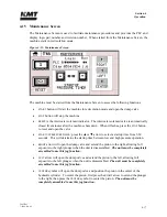


Section 5
Low Pressure Water System
20428712
10-2007/Rev 04
5-6
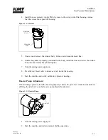
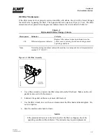
3.
Observe the discharge pressure from the booster pump. If the pressure stays below 90 psi
(6 bar), continue with Step 4.
4.
Stop the intensifier and remove the acorn nut on the side of the pump to access the
adjustment screw. It is normal for water to leak out when the acorn nut is removed.
5.
Use a flat screwdriver and turn the adjustment screw clockwise to increase the discharge
pressure or counter-clockwise to decrease the pressure. Adjust the pressure to the highest
desired pressure, within normal booster pump range.
If the adjustment screw is turned too far out (counter-clockwise) an internal spring
and relief will fall down inside the pump. If this occurs, the pump must be
removed and the parts must be reinstalled to avoid component damage.
6.
Replace the acorn nut, resume normal operation and observe the booster pressure. Peak
pressure should be in the range of 90 to 120 psi (6 to 8 bar). If not, repeat the adjustment
procedure.
Summary of Contents for STREAMLINE SL-V SRP 100
Page 23: ......
Page 25: ......
Page 174: ...Section 12 Parts List 20428786 2 2008 Rev 05 12 5 Figure 12 1 SL V SRP 100 Intensifier Unit ...
Page 176: ...Section 12 Parts List 20428786 2 2008 Rev 05 12 7 Figure 12 2 Intensifier Assembly ...
Page 184: ...Section 12 Parts List 20428786 2 2008 Rev 05 12 15 Figure 12 7 High Pressure Piping ...
Page 188: ...Section 12 Parts List 20428786 2 2008 Rev 05 12 19 Figure 12 9 Hydraulic Power Package ...
Page 190: ...Section 12 Parts List 20428786 2 2008 Rev 05 12 21 Figure 12 10 Motor Pump Assembly ...
Page 192: ...Section 12 Parts List 20428786 2 2008 Rev 05 12 23 Figure 12 11 Hydraulic Manifold Assembly ...
Page 194: ...Section 12 Parts List 20428786 2 2008 Rev 05 12 25 Figure 12 12 Hydraulic Hose Connections ...
Page 196: ...Section 12 Parts List 20428786 2 2008 Rev 05 12 27 Figure 12 13 Reservoir Assembly ...
Page 199: ...Section 12 Parts List 20428786 2 2008 Rev 05 12 30 Figure 12 14 Bulkhead Pipe Assembly ...
Page 201: ...Section 12 Parts List 20428786 2 2008 Rev 05 12 32 Figure 12 15 Cover Assembly ...
Page 205: ...Section 12 Parts List 20428786 2 2008 Rev 05 12 36 Figure 12 17 Electrical Assembly 230 50 60 ...
Page 223: ...Section 12 Parts List 20428786 2 2008 Rev 05 12 54 Figure 12 25 High Pressure Transducer ...
Page 224: ......
Page 225: ......
Page 226: ......
Page 227: ......
Page 228: ......
Page 229: ......
Page 230: ......
Page 231: ......
Page 232: ......
Page 233: ......
Page 234: ......
Page 235: ......
Page 236: ......
Page 237: ......
Page 238: ......
Page 239: ......


