


Section 9
High Pressure Water System
20428754
7-2007/Rev 03
9-22
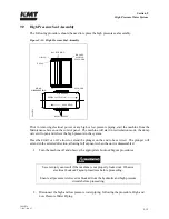
Severe injury can result if the machine is not properly locked out. Observe
electrical Lockout/Tagout procedures before proceeding.
Ensure all pressure is relieved or blocked from the hydraulic and high pressure
circuits before proceeding.
2.
Disconnect the high and low pressure water piping, following the procedure, High and
Low Pressure Water Piping.
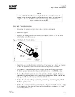
3.
Remove the proximity switch on the end of the hydraulic cylinder to be serviced. This
will allow the hydraulic oil to drain back to the reservoir, minimizing oil spillage. It will
take approximately five minutes for the oil to drain.
4.
Remove the high pressure cylinder assembly, following the procedure, High Pressure
Cylinder Assembly Removal.
5.
Use a flat screwdriver to remove the retaining ring from the hydraulic cylinder head.
6.
Remove the bushing retainer flange and clean the surfaces, weep holes and grooves.
Check the retainer flange for cracks.
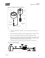
7.
Replace the proximity switch by positioning the o-ring spacer and the switch. Apply
JL-M grease to the threads on the socket head screws and tighten, following the torque
specifications in Table 9-2.
It is recommended that the proximity switch be reinstalled as soon as practical.
Removal of the switch presents the potential of an oil spray hazard.
Ensure that the proximity switch is properly installed and secured prior to starting
the machine. Failure to tighten the two hold down screws on each switch will
result in the spray of hydraulic oil.
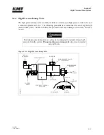
8.
Thread the large end of the cartridge removal tool onto the hydraulic cartridge seal and
pull the cartridge out, over the plunger.
Summary of Contents for STREAMLINE SL-V SRP 100
Page 23: ......
Page 25: ......
Page 174: ...Section 12 Parts List 20428786 2 2008 Rev 05 12 5 Figure 12 1 SL V SRP 100 Intensifier Unit ...
Page 176: ...Section 12 Parts List 20428786 2 2008 Rev 05 12 7 Figure 12 2 Intensifier Assembly ...
Page 184: ...Section 12 Parts List 20428786 2 2008 Rev 05 12 15 Figure 12 7 High Pressure Piping ...
Page 188: ...Section 12 Parts List 20428786 2 2008 Rev 05 12 19 Figure 12 9 Hydraulic Power Package ...
Page 190: ...Section 12 Parts List 20428786 2 2008 Rev 05 12 21 Figure 12 10 Motor Pump Assembly ...
Page 192: ...Section 12 Parts List 20428786 2 2008 Rev 05 12 23 Figure 12 11 Hydraulic Manifold Assembly ...
Page 194: ...Section 12 Parts List 20428786 2 2008 Rev 05 12 25 Figure 12 12 Hydraulic Hose Connections ...
Page 196: ...Section 12 Parts List 20428786 2 2008 Rev 05 12 27 Figure 12 13 Reservoir Assembly ...
Page 199: ...Section 12 Parts List 20428786 2 2008 Rev 05 12 30 Figure 12 14 Bulkhead Pipe Assembly ...
Page 201: ...Section 12 Parts List 20428786 2 2008 Rev 05 12 32 Figure 12 15 Cover Assembly ...
Page 205: ...Section 12 Parts List 20428786 2 2008 Rev 05 12 36 Figure 12 17 Electrical Assembly 230 50 60 ...
Page 223: ...Section 12 Parts List 20428786 2 2008 Rev 05 12 54 Figure 12 25 High Pressure Transducer ...
Page 224: ......
Page 225: ......
Page 226: ......
Page 227: ......
Page 228: ......
Page 229: ......
Page 230: ......
Page 231: ......
Page 232: ......
Page 233: ......
Page 234: ......
Page 235: ......
Page 236: ......
Page 237: ......
Page 238: ......
Page 239: ......


