


Section 7
Hydraulic System
20428738
11-2005/Rev 01
7-2
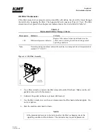
7.2
Optional System Components
Optional proportional pressure control enhances the standard high and low pressure selection by
allowing the operator to select or vary the hydraulic operating pressure from the control panel or
from a remote console. From the Pressure Control Screen the high pressure can be set as a
percentage, from 0% to 100%. An electronically controlled hydraulic cartridge valve receives a
signal from the PLC and automatically makes the operator selected adjustments.
As proportional pressure controls hydraulic oil pressure, it also determines cutting water pressure
based on the intensification ratio.
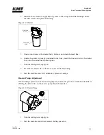
7.3
Operation
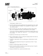
The electric motor drives three pumps mounted in tandem; the main hydraulic pump, the
recirculation pump and the booster pump. The motor drives the variable displacement, pressure
compensated hydraulic pump by means of a flexible coupling.
Hydraulic fluid from the reservoir is drawn into the inlet, low pressure side of the hydraulic
pump. Oil delivered to the pump should be maintained at 110-115
°
F (43-46
°
C). Hydraulic
fluid then enters the bottom of the manifold through an internal anti-rotation check valve. After a
shutdown, the anti-rotation check valve prevents the pump from running backwards.
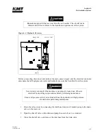
Figure 7-2: Hydraulic System Components
ELECTRIC
MOTOR
HYDRAULIC
PUMP
MAIN SYSTEM
RELIEF VALVE
CASE DRAIN
HIGH/LOW LIMIT
COMPENSATORS
HIGH PRESSURE
CONTROL VALVE
LOW PRESSURE
CONTROL VALVE
HYDRAULIC
REFERENCE GAUGE
DIRECTIONAL
CONTROL
VALVE
HYDRAULIC
MANIFOLD
0
511
819
5
SOLENOID
VALVE
Summary of Contents for STREAMLINE SL-V SRP 100
Page 23: ......
Page 25: ......
Page 174: ...Section 12 Parts List 20428786 2 2008 Rev 05 12 5 Figure 12 1 SL V SRP 100 Intensifier Unit ...
Page 176: ...Section 12 Parts List 20428786 2 2008 Rev 05 12 7 Figure 12 2 Intensifier Assembly ...
Page 184: ...Section 12 Parts List 20428786 2 2008 Rev 05 12 15 Figure 12 7 High Pressure Piping ...
Page 188: ...Section 12 Parts List 20428786 2 2008 Rev 05 12 19 Figure 12 9 Hydraulic Power Package ...
Page 190: ...Section 12 Parts List 20428786 2 2008 Rev 05 12 21 Figure 12 10 Motor Pump Assembly ...
Page 192: ...Section 12 Parts List 20428786 2 2008 Rev 05 12 23 Figure 12 11 Hydraulic Manifold Assembly ...
Page 194: ...Section 12 Parts List 20428786 2 2008 Rev 05 12 25 Figure 12 12 Hydraulic Hose Connections ...
Page 196: ...Section 12 Parts List 20428786 2 2008 Rev 05 12 27 Figure 12 13 Reservoir Assembly ...
Page 199: ...Section 12 Parts List 20428786 2 2008 Rev 05 12 30 Figure 12 14 Bulkhead Pipe Assembly ...
Page 201: ...Section 12 Parts List 20428786 2 2008 Rev 05 12 32 Figure 12 15 Cover Assembly ...
Page 205: ...Section 12 Parts List 20428786 2 2008 Rev 05 12 36 Figure 12 17 Electrical Assembly 230 50 60 ...
Page 223: ...Section 12 Parts List 20428786 2 2008 Rev 05 12 54 Figure 12 25 High Pressure Transducer ...
Page 224: ......
Page 225: ......
Page 226: ......
Page 227: ......
Page 228: ......
Page 229: ......
Page 230: ......
Page 231: ......
Page 232: ......
Page 233: ......
Page 234: ......
Page 235: ......
Page 236: ......
Page 237: ......
Page 238: ......
Page 239: ......


