


CEMOR Monitor Suspension System
Revision 1
69
18.2
Connecting the Power Supply
The number of cables differs depending on the CEMOR version. The connection procedure is
described here based on the maximum equipment that can be fitted onto the CEMOR 8 model.
The power cables are not included in the scope of delivery and must be provided by the
customer according to the specifications of the TFT screens. The illustration shows an example
for the power supply.
•
Observe the safety notes, see section 18.1 “Safety Notes”, page 68.
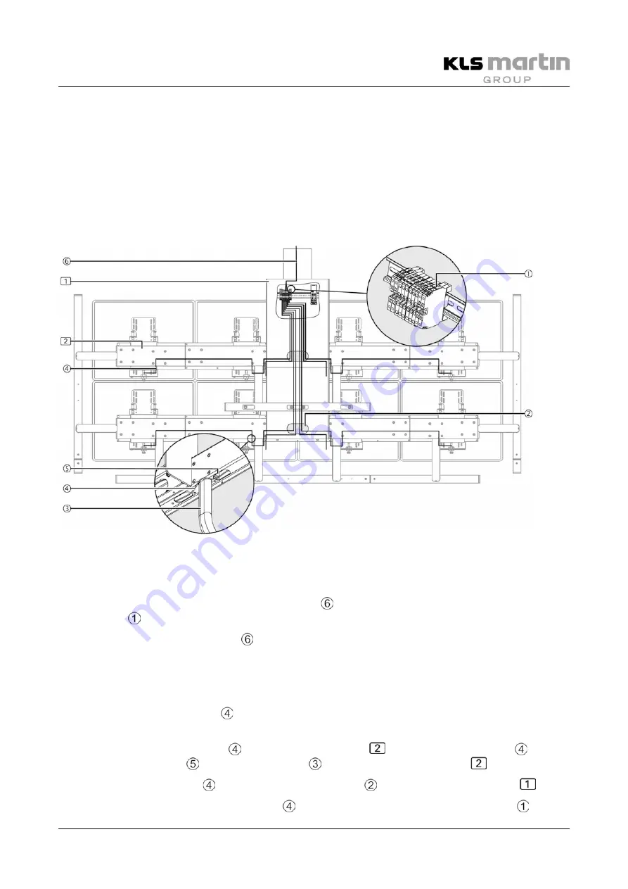
Fig. 18-1:
Connecting the power supply
18.2.1
Connecting the CEMOR Power Supply Cables Provided by the Customer
•
Place the strands of the power supply cables on the connections of the serial
terminal .
•
Lead the power supply cables to the interface plate according to the Mounting
Instructions of the suspension arm system.
18.2.2
Connecting the Power Supply Cables of the TFT Screens
•
Connect the power cables to the TFT screens according to the Mounting Instructions of
the manufacturer of the TFT screen.
•
Introduce the power cables into the mounting rails
. Lead the power cables out of
the mounting holes around the handles
and into the mounting rails
again.
•
Lead the power cables through the mounting hole into the supporting frame
.
•
Place the strands of the power cables on the connections of the serial terminal .
Summary of Contents for CEMOR
Page 73: ...Mounting Instructions 0BCEMOR Monitor Suspension System Revision 1 73 19 1 2 CEMOR 6...
Page 74: ...Mounting Instructions 0BCEMOR Monitor Suspension System 74 Revision 1 19 1 3 CEMOR 8...
Page 75: ...Mounting Instructions 0BCEMOR Monitor Suspension System Revision 1 75 19 1 4 CEMOR LS...
Page 83: ...Mounting Instructions 0BCEMOR Monitor Suspension System Revision 1 83...


