30
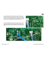
3) Power supply adjustment (KiwiSix upgrade power board).
Using an accurate 4 1/2 digit or better DVM check and trim the +15v, +5v, -15v and -5v power in this order (red arrows). The test points for connecting the
DVM are clearly marked on the top left of the power supply board. To adjust these you will require a small screwdriver. The +15v and -15v should be ±50mv
and the +5v and -5v should be ±10mv.
KLM-366
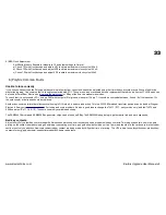
4) VCF Offset Adjustment
Obtain ground at TP5 (upper left of picture). Set the Waveform to PW and PWM to 10. Connect the DVM to the collector of Q5. For each voice adjust VR7
(green arrow) so that 0v is is measured at the collector of Q5 (Red arrow) (see diagram). The voice 0 & 1 are
shown in the picture and the other voices are the same.
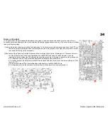
5) VCA Level Adjustment
Set Octave to 4. Leave other settings at the normal settings. Connect the oscilloscope to TP1 Signal Out
(top left in picture). Play C3 (1 oct below middle C) and adjust VR9 (blue arrow) to obtain a 1v peak to peak
waveform at TP1 (±5%). Do this for each voice.
www.kiwitechnics.com
KiwiSix Upgrade User Manual v3


