35
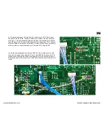
3) Isolate the mounting leg of the Keyboard from the grounding foil running under the KLM-368 FX Board. This is best done by cutting out a square of the foil around
the keyboard mounting leg.
4) Fit the supplied ferrite clamps onto the keyboard scan lines and the front panel switch scan lines. The Keyboard scan lines run from the voice board to the left
hand end of the keyboard and are usually black & white. The front panel scan lines run from the Kiwisix board from CN6 and are usually blue in colour.
7) PolySix Waveform Mod
Saw + PW Wave Combination Mod
A very simple waveform mod can be made to the Polysix. This was developed by Johannes Hausensteiner. By removing Diode D1 on the KLM-366 board the Polysix
will combine both the Saw & PW waveforms with the PW level controlled by the PW knob. With the PW set to full only the Saw remains so it is possible to mix the two
waveforms.
7) PolySix Hold Pedal Mod
Hold Pedal in the CHORD input on the rear of the PolySix Mod
A mod can be made that will allow a HOLD pedal to be used into the CHORD input on the rear of the PolySix. This involves a track cut and a wire to be run. This mod
will only have any effect with version 3+ of the firmware.
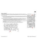
1) Cut the track joining D3 on the voice board topside.
See left photo.
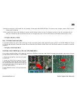
2) Join the Leg of D3 to Pin 32 of the blue CPU socket
on the underside of the voice board. See right photo.
We have used enamelled copper wire but any thin wire
can be used. Be careful not to short together the CPU
pins when soldering the wire.
Any pedal that shorts the tip to the ring when pressed
will work.
www.kiwitechnics.com
KiwiSix Upgrade User Manual v3


