26
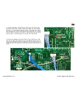
d) Cut the trace between -5v & pin2 and the -5v and pin 4 of IC2. This is done
underneath IC2 where the -5v track runs down the center of IC2 and links pin2,
pin4 & pin 7. Cut the track neatly between pin 2 and the track and pin 4 and the
track leading to pin 7 (arrows in photo shows cuts already made). Pin 7 needs to
stay connected to this track so cut carefully. To make sure you have cut correctly
make sure there is no short between pin 7 and pins 2 & 4 using a DVM.
e) Add the short supplied wire between CN09 Pin 3 & pin 6 (Blue arrows). Add
the one of the longer wires between IC2 pin 2 and CN09 Pin5 at the end of R16
(yellow arrows) and the other longer wire between IC2 pin 4 and the left end of
R18 (purple arrows). The gray wires to CN13 have been removed in the photo for
clarity.
www.kiwitechnics.com
KiwiSix Upgrade User Manual v3


