Operation Instruction
CI-1
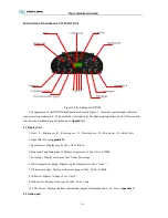
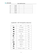
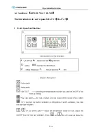
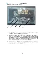
Illustration of switch and indicator
Number of switches , indicators and their own positions may vary with the vehicle model and configuration
state, please refer to the flowing sheet :
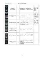
Switch
Name
Color
Function
Notes
Retarder foot control
function release switch
White
Pressed on up: foot control function is
turned ON
Pressed on bottom: foot control function is
turned OFF
Daylight lamp
White
Pressed on top: interior lighting OFF
Pressed on bottom: interior lighting ON
Hazard alarm lamp
Red
Pressed on bottom: all turning indication
lamps will turn on
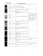
Luggage compartment
lamp
White
Pressed on top: the luggage cabin lamp OFF
Pressed on bottom: the luggage cabin lamp
ON
Ventilator
White
Pressed on top: the ventilator is turned off
Pressed on bottom: the ventilator is turned
on
Front fog lamp
White
Pressed on top: the front fog lamp OFF
Pressed on bottom: the front fog lamp ON
Rear fog lamp
White
Pressed on top: the rear fog lamp OFF
Pressed on bottom: the rear fog lamp ON
Reading lamp
White
Pressed on top: the reading lamp OFF
Pressed on bottom: the reading lamp ON
Front windshield
defrosting switch
White
Pressed on top: turn off defrosting function
Pressed on bottom: turn on defrosting
function
Summary of Contents for XMQ6127 series
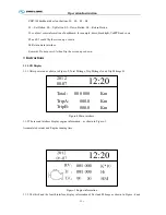
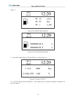
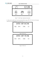
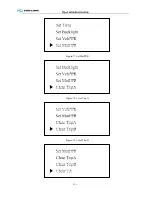
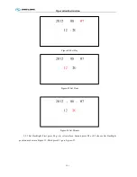
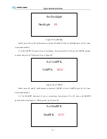
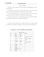
Page 18: ...Operation Instruction CI 1 Figure 17 Set MotPPR Figure 18 Clear Trip A Figure 19 Clear Trip B...
Page 32: ...Operation Instruction P A 1 2 Control panel operation...
Page 33: ...Operation Instruction P A 1...
Page 34: ...Operation Instruction P A 1...
Page 35: ...Operation Instruction P A 1...
Page 36: ...Operation Instruction P A 1...
Page 41: ...Operation Instruction 0 G 1 1 1 2 2 Pushbutton Settings...
Page 42: ...Operation Instruction 0 G 1 1 2 Starting the Engine 1 3 Selecting the Gear...
Page 43: ...Operation Instruction 0 G 1 1 4 Setting Off 1 5 Driving Ranges...
Page 44: ...Operation Instruction 0 G 1 1 5 1 Downhill Travel 1 5 2 Downhill Travel 1 5 3 Kickdown...
Page 46: ...Operation Instruction 0 G 1 1 6 Stopping Parking...
Page 51: ...Operation Instruction 0 G 1 1 11 1 Limp Home Mode 1 12 Auxiliary Control Unit...
Page 52: ...Operation Instruction 0 G 1 1 12 1 Operating Instructions for the Auxiliary Control Unit...
Page 53: ...Operation Instruction 0 AB 1 WABCO ABS BASIC INTRODUCTION...
Page 54: ...Operation Instruction 0 AB 1...
Page 55: ...Operation Instruction 0 AB 1...
Page 56: ...Operation Instruction 0 AB 1...
Page 57: ...Operation Instruction 0 AB 1...
Page 58: ...Operation Instruction 0 EC 1 ECAS System Introduction 1 System introduction...
Page 59: ...Operation Instruction 0 EC 1 3 System function...
Page 60: ...Operation Instruction 0 EC 1...
Page 77: ...Operation Instruction 0 E 1 CAN bus module...
Page 158: ...Appendix A 4 Air braking schematic diagram...
Page 159: ...A 5 Electric schematic diagram of the complete vehicle 1...
Page 160: ...A 6 Electric schematic diagram of the complete vehicle 2...
Page 161: ...A 7 Electric schematic diagram of the complete vehicle 3...
Page 162: ...A 8 Electric schematic diagram of the complete vehicle 4...

