Operation Instruction
OI-4
Ignition switch
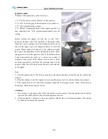
Position of the ignition key is shown in fig.1.
1."L" LOCK: Insert or remove the key in this position.
2."A" ACC: Power supply of the instrument is switched on
3."O" ON: Normal driving position
4."S" START: Initiating position of the engine, and the key
may rebound to the "ON" position automatically after the
startup
.
Before starting the engine, turn the key to the “ACC”
position and then to the “ON” position. At this point, three
lights (red, yellow and green) on the dashboard will come on.
Wait for the lights to go out completely before you start the
engine. Please make sure that all of the self-check lights
have gone out completely before starting the engine. Allow
the engine to run at idle speed for three to five minutes after
it has been started; but never let it run for more than 10
minutes at idle speed. If the vehicle does not move, press
accelerator modestly to increase the rotational speed of the
engine a little; this will also prevent the early wear and tear
of the engine.
Note
:
1. Turn the ignition key to the OFF position after the engine has been turned off and the vehicle has
stopped .
2. If the first attempt to start the engine is not successful, please wait two minutes before trying again.
3. If the engine fails to start after three attempts, check the fuel supply system. If the vehicle runs on
natural gas, check the gas supply system.
Attention!
1.
Do not remove the ignition key while the vehicle is in movement. And the ignition key should be
turned to the LOCK position only after the engine shut down.
2.
When leaving the vehicle, even for a short period, take the key out to avoid operation of the vehicle
by children or unauthorized persons.
1
Summary of Contents for XMQ6127 series
Page 18: ...Operation Instruction CI 1 Figure 17 Set MotPPR Figure 18 Clear Trip A Figure 19 Clear Trip B...
Page 32: ...Operation Instruction P A 1 2 Control panel operation...
Page 33: ...Operation Instruction P A 1...
Page 34: ...Operation Instruction P A 1...
Page 35: ...Operation Instruction P A 1...
Page 36: ...Operation Instruction P A 1...
Page 41: ...Operation Instruction 0 G 1 1 1 2 2 Pushbutton Settings...
Page 42: ...Operation Instruction 0 G 1 1 2 Starting the Engine 1 3 Selecting the Gear...
Page 43: ...Operation Instruction 0 G 1 1 4 Setting Off 1 5 Driving Ranges...
Page 44: ...Operation Instruction 0 G 1 1 5 1 Downhill Travel 1 5 2 Downhill Travel 1 5 3 Kickdown...
Page 46: ...Operation Instruction 0 G 1 1 6 Stopping Parking...
Page 51: ...Operation Instruction 0 G 1 1 11 1 Limp Home Mode 1 12 Auxiliary Control Unit...
Page 52: ...Operation Instruction 0 G 1 1 12 1 Operating Instructions for the Auxiliary Control Unit...
Page 53: ...Operation Instruction 0 AB 1 WABCO ABS BASIC INTRODUCTION...
Page 54: ...Operation Instruction 0 AB 1...
Page 55: ...Operation Instruction 0 AB 1...
Page 56: ...Operation Instruction 0 AB 1...
Page 57: ...Operation Instruction 0 AB 1...
Page 58: ...Operation Instruction 0 EC 1 ECAS System Introduction 1 System introduction...
Page 59: ...Operation Instruction 0 EC 1 3 System function...
Page 60: ...Operation Instruction 0 EC 1...
Page 77: ...Operation Instruction 0 E 1 CAN bus module...
Page 158: ...Appendix A 4 Air braking schematic diagram...
Page 159: ...A 5 Electric schematic diagram of the complete vehicle 1...
Page 160: ...A 6 Electric schematic diagram of the complete vehicle 2...
Page 161: ...A 7 Electric schematic diagram of the complete vehicle 3...
Page 162: ...A 8 Electric schematic diagram of the complete vehicle 4...

