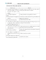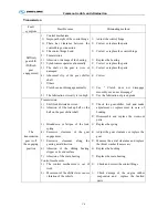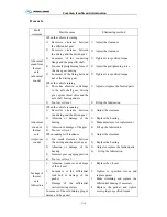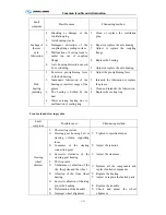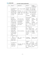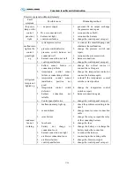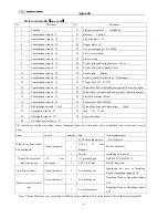
Common trouble and elimination
C-15
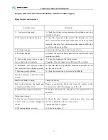
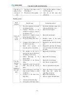
Fault
symptom
Possible cause
Eliminating method
Unsteady
braking
1.
Tire pressure uneven or tire
dimension different
2.
Improper installation of the
brake shoe or damage of the
return spring
3.
Improper engagement of the
braking friction lining
4.
Improper adjustment of the left
and right brake
5.
Deterioration of the braking
friction lining
6.
Oil on the braking friction
lining
7.
Damage of the brake backing
plate
8.
Looseness of the leaf spring
U-bolt
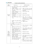
1.
Operate as required
2.
Tighten the locknut of the brake
shoe supporting pin and replace the
return spring
3.
Adjust the friction lining
4.
Adjust the brake
5.
Replace the friction lining
6.
Clean with the gasoline to
eliminate the effect of the leakage
at the hub oil seal, oil cylinder
cover and the rubber cap
7.
Replace it
8.
Tighten the U-bolt
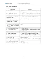
The
braking
can't be
applied
under all
conditions
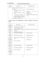
When compressed air pressure is
normal:
1.
Too short of the brake valve
travel
2.
The camshaft doesn't rotate (the
bushing is lack of lubricant)
3.
Improper adjustment of the
braking chamber pusher stroke
4.
Improper sliding contact of the
relay valve
5.
Overheat or deterioration of the
braking friction lining
6.
Improper engagement of the
braking friction lining
7.
There has lubricant on the
friction lining or the brake drum
8.
Water entering brake drum
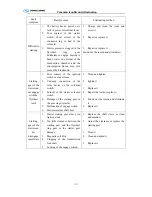
1.
Check ,and replace the braking
valve if necessary
2.
Check working condition of the
camshaft and replace it as needed
3.
Adjust the travel
4.
Disassemble and repair
5.
Replace the friction lining
6.
Adjust engagement position of the
friction lining
7.
Clean the oil trace with proper
cleanser or replace the friction
lining
8.
Drying out the water by pressing
the pedal gently during the running
Summary of Contents for XMQ6127 series
Page 18: ...Operation Instruction CI 1 Figure 17 Set MotPPR Figure 18 Clear Trip A Figure 19 Clear Trip B...
Page 32: ...Operation Instruction P A 1 2 Control panel operation...
Page 33: ...Operation Instruction P A 1...
Page 34: ...Operation Instruction P A 1...
Page 35: ...Operation Instruction P A 1...
Page 36: ...Operation Instruction P A 1...
Page 41: ...Operation Instruction 0 G 1 1 1 2 2 Pushbutton Settings...
Page 42: ...Operation Instruction 0 G 1 1 2 Starting the Engine 1 3 Selecting the Gear...
Page 43: ...Operation Instruction 0 G 1 1 4 Setting Off 1 5 Driving Ranges...
Page 44: ...Operation Instruction 0 G 1 1 5 1 Downhill Travel 1 5 2 Downhill Travel 1 5 3 Kickdown...
Page 46: ...Operation Instruction 0 G 1 1 6 Stopping Parking...
Page 51: ...Operation Instruction 0 G 1 1 11 1 Limp Home Mode 1 12 Auxiliary Control Unit...
Page 52: ...Operation Instruction 0 G 1 1 12 1 Operating Instructions for the Auxiliary Control Unit...
Page 53: ...Operation Instruction 0 AB 1 WABCO ABS BASIC INTRODUCTION...
Page 54: ...Operation Instruction 0 AB 1...
Page 55: ...Operation Instruction 0 AB 1...
Page 56: ...Operation Instruction 0 AB 1...
Page 57: ...Operation Instruction 0 AB 1...
Page 58: ...Operation Instruction 0 EC 1 ECAS System Introduction 1 System introduction...
Page 59: ...Operation Instruction 0 EC 1 3 System function...
Page 60: ...Operation Instruction 0 EC 1...
Page 77: ...Operation Instruction 0 E 1 CAN bus module...
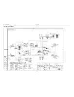
Page 158: ...Appendix A 4 Air braking schematic diagram...
Page 159: ...A 5 Electric schematic diagram of the complete vehicle 1...
Page 160: ...A 6 Electric schematic diagram of the complete vehicle 2...
Page 161: ...A 7 Electric schematic diagram of the complete vehicle 3...
Page 162: ...A 8 Electric schematic diagram of the complete vehicle 4...

