Vehicle Starting and Driving
S-3
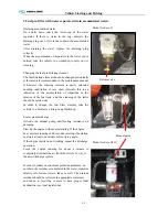
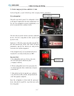
3 Fuel pre-filter with water separator (drain accumulated water)
Draining accumulated water
On a daily basis, check the lower cup of the water
separator. If there is water in the cup, unscrew the
draining plug one or two turns, to drain the accumulated
water.
After draining the water, tighten the draining plug
correctly.
When the accumulation of impurities in the lower cup is
noticed, take the vehicle to a workshop to carry out its
cleaning.
Changing the fuel pre-filtering element
The fuel filtering element should be changed periodically,
at the intervals recommended in the maintenance manual.
If however, the filtering element is easily saturated
needing substitution at very short intervals, this is an
indication of the accumulation of impurities in the
interior of the fuel tank, and the cleaning of the latter
should be carried out.
In order to change the fuel filter element, take the
vehicle to a Dealer or a King-Long Workshop.
Fuel system discharge
Activate the manual pump until feeling resistance on
pumping.
Start up the engine without accelerating. If the engine
does not start running in 20 seconds, interrupt the startup
and wait at least one minute before trying again.
If the engine insists on not working, repeat the discharge
operation.
Leave the engine running for about a minute to
completely eliminate the air from the system by way of
the auto-discharge system.
In order to reduce environment pollution problems, do
not drain the residues accumulated in the water separator
directly into Nature (rivers, lakes or soil). The drained
residues should be collected in appropriate containers
and taken to receiving centers to have proper final
destination (see local legislation).
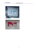
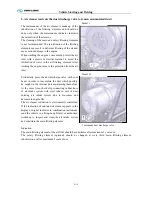
Model for Euro II
Model for Euro III IV
Manual pump
Release valve
Summary of Contents for XMQ6127 series
Page 18: ...Operation Instruction CI 1 Figure 17 Set MotPPR Figure 18 Clear Trip A Figure 19 Clear Trip B...
Page 32: ...Operation Instruction P A 1 2 Control panel operation...
Page 33: ...Operation Instruction P A 1...
Page 34: ...Operation Instruction P A 1...
Page 35: ...Operation Instruction P A 1...
Page 36: ...Operation Instruction P A 1...
Page 41: ...Operation Instruction 0 G 1 1 1 2 2 Pushbutton Settings...
Page 42: ...Operation Instruction 0 G 1 1 2 Starting the Engine 1 3 Selecting the Gear...
Page 43: ...Operation Instruction 0 G 1 1 4 Setting Off 1 5 Driving Ranges...
Page 44: ...Operation Instruction 0 G 1 1 5 1 Downhill Travel 1 5 2 Downhill Travel 1 5 3 Kickdown...
Page 46: ...Operation Instruction 0 G 1 1 6 Stopping Parking...
Page 51: ...Operation Instruction 0 G 1 1 11 1 Limp Home Mode 1 12 Auxiliary Control Unit...
Page 52: ...Operation Instruction 0 G 1 1 12 1 Operating Instructions for the Auxiliary Control Unit...
Page 53: ...Operation Instruction 0 AB 1 WABCO ABS BASIC INTRODUCTION...
Page 54: ...Operation Instruction 0 AB 1...
Page 55: ...Operation Instruction 0 AB 1...
Page 56: ...Operation Instruction 0 AB 1...
Page 57: ...Operation Instruction 0 AB 1...
Page 58: ...Operation Instruction 0 EC 1 ECAS System Introduction 1 System introduction...
Page 59: ...Operation Instruction 0 EC 1 3 System function...
Page 60: ...Operation Instruction 0 EC 1...
Page 77: ...Operation Instruction 0 E 1 CAN bus module...
Page 158: ...Appendix A 4 Air braking schematic diagram...
Page 159: ...A 5 Electric schematic diagram of the complete vehicle 1...
Page 160: ...A 6 Electric schematic diagram of the complete vehicle 2...
Page 161: ...A 7 Electric schematic diagram of the complete vehicle 3...
Page 162: ...A 8 Electric schematic diagram of the complete vehicle 4...


