Maintenance and service
M-18
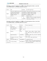
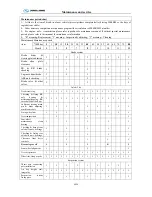
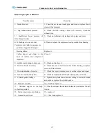
System Item Operation Technical requirement
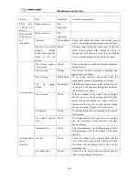
The air
suspension
The rubber bal
joints
Change
There are gaps on the surface of the rubber
The surface of the rubber become adhesive, brittle and the rubbe
drop off seriously
The connection of the metal and the rubber is damaged. The partia
depth is up to 6mm
The rubber ball joint rotates in the inner hole of the ball head a
will
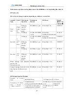
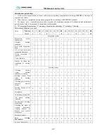
The heigh
control valve.
Check
adjust
Check the equilibrium position of the adjustment bar of the heigh
control valve.
The rubber of
The link rod
Change
Change it if the rubber of link rod becomes ageing, brittle, adhesive
and lose its elasticity
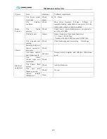
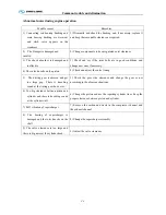
The
connecting
members of
the shock
absorber
Check
change
Check the connecting members of the shock absorber if they are
damaged please adjust or change them.
the rubber
Check
change
If the rubber is crack, brittle, adhesive and loses its elasticity please
adjust or change them.
The height
Check
adjust
Charge the air springs and adjust to the design height, then check
the wheel base, the height of the vehicle body and the two side’
wheels’ locations which are relative to the frame. If it is necessary
please adjust the height of the air springs and the length of the rod
in order to arrive to the design request
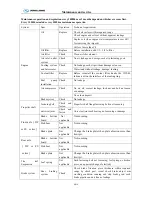
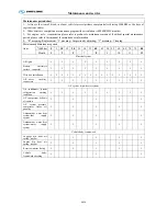
Brake system
Brake pedal
free stroke
Check Break pedal free stroke 12
~
15mm
Brake valve
and pipe joint
Check
and
fasten
Break valve and pipe joint connection reliable and without air
leakage
ABS system
Check
ABS working properly
Auxiliary
brake, stop
brake free
stroke
Check Effective, 20% dual direction stopping at slop reliable
Retarder
Check
Retarder working properly
Engine
exhaust brake
Check
Exhaust brake working properly
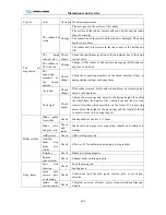
Body, frame
door lock
function
Check
Lock function good
Sealing good
cabin door
sustain pole
or air spring
Check
Cabin door lock function good, sustain pole or air spring
effective
inside and
outside mirror
Check
Complete, no crack, effective, mirror clean, installation firm and
reliable
Summary of Contents for XMQ6127 series
Page 18: ...Operation Instruction CI 1 Figure 17 Set MotPPR Figure 18 Clear Trip A Figure 19 Clear Trip B...
Page 32: ...Operation Instruction P A 1 2 Control panel operation...
Page 33: ...Operation Instruction P A 1...
Page 34: ...Operation Instruction P A 1...
Page 35: ...Operation Instruction P A 1...
Page 36: ...Operation Instruction P A 1...
Page 41: ...Operation Instruction 0 G 1 1 1 2 2 Pushbutton Settings...
Page 42: ...Operation Instruction 0 G 1 1 2 Starting the Engine 1 3 Selecting the Gear...
Page 43: ...Operation Instruction 0 G 1 1 4 Setting Off 1 5 Driving Ranges...
Page 44: ...Operation Instruction 0 G 1 1 5 1 Downhill Travel 1 5 2 Downhill Travel 1 5 3 Kickdown...
Page 46: ...Operation Instruction 0 G 1 1 6 Stopping Parking...
Page 51: ...Operation Instruction 0 G 1 1 11 1 Limp Home Mode 1 12 Auxiliary Control Unit...
Page 52: ...Operation Instruction 0 G 1 1 12 1 Operating Instructions for the Auxiliary Control Unit...
Page 53: ...Operation Instruction 0 AB 1 WABCO ABS BASIC INTRODUCTION...
Page 54: ...Operation Instruction 0 AB 1...
Page 55: ...Operation Instruction 0 AB 1...
Page 56: ...Operation Instruction 0 AB 1...
Page 57: ...Operation Instruction 0 AB 1...
Page 58: ...Operation Instruction 0 EC 1 ECAS System Introduction 1 System introduction...
Page 59: ...Operation Instruction 0 EC 1 3 System function...
Page 60: ...Operation Instruction 0 EC 1...
Page 77: ...Operation Instruction 0 E 1 CAN bus module...
Page 158: ...Appendix A 4 Air braking schematic diagram...
Page 159: ...A 5 Electric schematic diagram of the complete vehicle 1...
Page 160: ...A 6 Electric schematic diagram of the complete vehicle 2...
Page 161: ...A 7 Electric schematic diagram of the complete vehicle 3...
Page 162: ...A 8 Electric schematic diagram of the complete vehicle 4...

