Appendix
A-2
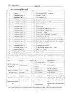
Bolts torque table
Torques for bolts with metric unified threads
Dimension of bolt
Torques N.m*(ft-lb)
8.8 10.9
12.9
M4 3(2)
5(3)
5(4)
M5 6(4)
9(7)
10(7)
M6 10(7)
15(11)
18(13)
M8 25(18)
35(26)
45(33)
M10 50(37)
75(55)
83(61)
M12 88(65)
123(91)
147(108)
M14 137(101)
196(145) 235(173)
M16 211(156)
300(221)
358(264)
M18 290(213)
412(303) 490(361)
M20 412(304)
578(426) 696(513)
M22 560(413)
785(559) 942(695)
M24 711(524)
1000(738)
1200(885)
M27 1050(774)
1480(1092)
1774(1308)
M30 1420(1047)
2010(1482)
2400(1770)
Torques for bolts with metric fine threads
Dimension of bolt
Torques N.m*(ft-lb)
8.8 10.9
12.9
M8×1 26(19)
37(27) 48(35)
M10×1.25 52(38)
76(56) 88(65)
M12×1.25 98(72)
137(101)
126(119)
M12×1.5 93(69)
127(94)
152(112)
M14×1.5 152(112)
216(159) 255(188)
M16×1.5 225(166)
318(235) 383(282)
M18×1.5 324(239)
466(344) 554(409)
M20×1.5 461(340)
628(463) 775(572)
M22×1.5 618(456)
863(636)
1058(780)
M24×2 780(575)
1096(808)
1294(954)
M27×2 1147(846)
1578(1164)
1920(1416)
M30×2 1568(1156)
2254(1662)
2695(1988)
The torque values allow bolt yield strength up to 90%, assuming a friction coefficient of
μ
Summary of Contents for XMQ6127 series
Page 18: ...Operation Instruction CI 1 Figure 17 Set MotPPR Figure 18 Clear Trip A Figure 19 Clear Trip B...
Page 32: ...Operation Instruction P A 1 2 Control panel operation...
Page 33: ...Operation Instruction P A 1...
Page 34: ...Operation Instruction P A 1...
Page 35: ...Operation Instruction P A 1...
Page 36: ...Operation Instruction P A 1...
Page 41: ...Operation Instruction 0 G 1 1 1 2 2 Pushbutton Settings...
Page 42: ...Operation Instruction 0 G 1 1 2 Starting the Engine 1 3 Selecting the Gear...
Page 43: ...Operation Instruction 0 G 1 1 4 Setting Off 1 5 Driving Ranges...
Page 44: ...Operation Instruction 0 G 1 1 5 1 Downhill Travel 1 5 2 Downhill Travel 1 5 3 Kickdown...
Page 46: ...Operation Instruction 0 G 1 1 6 Stopping Parking...
Page 51: ...Operation Instruction 0 G 1 1 11 1 Limp Home Mode 1 12 Auxiliary Control Unit...
Page 52: ...Operation Instruction 0 G 1 1 12 1 Operating Instructions for the Auxiliary Control Unit...
Page 53: ...Operation Instruction 0 AB 1 WABCO ABS BASIC INTRODUCTION...
Page 54: ...Operation Instruction 0 AB 1...
Page 55: ...Operation Instruction 0 AB 1...
Page 56: ...Operation Instruction 0 AB 1...
Page 57: ...Operation Instruction 0 AB 1...
Page 58: ...Operation Instruction 0 EC 1 ECAS System Introduction 1 System introduction...
Page 59: ...Operation Instruction 0 EC 1 3 System function...
Page 60: ...Operation Instruction 0 EC 1...
Page 77: ...Operation Instruction 0 E 1 CAN bus module...
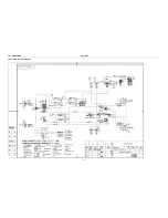
Page 158: ...Appendix A 4 Air braking schematic diagram...
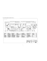
Page 159: ...A 5 Electric schematic diagram of the complete vehicle 1...
Page 160: ...A 6 Electric schematic diagram of the complete vehicle 2...
Page 161: ...A 7 Electric schematic diagram of the complete vehicle 3...
Page 162: ...A 8 Electric schematic diagram of the complete vehicle 4...

