Maintenance and service
M-10
Breaking-in of New Vehicle
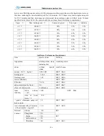
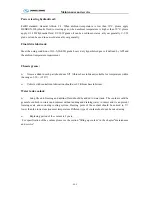
Engine of new vehicle should be sure not to operate at the maximum power output during the
breaking-in period to keep best performance and superior efficiency as well as guarantee durable service
life. Please drive cautiously and pay more attention to abnormal phenomenon occurred during breaking-in
period. Given break-in mileage of the new vehicle is 5,000 km., please run at the speed under 100 km/h in
breaking-in period.
Preparation before breaking-in of the new vehicle
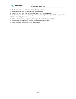
1. Wash the vehicle and check connection and tight situation of each place.
2. Check coolant storage in radiator and check each place of cooling system for leakage.
3. Check oil level of engine, clutch control system, transmission, drive axle, steering gear and clutch oil
storage tank. If deficient, add and then check each place for leakage.
4. Check and see if braking system works properly and leakage phenomenon exists at connections of all
valves and pipelines.
5. Check and see if phenomenon of loosing or clogging exists at each place of steering system.
6. Check and see if electric equipments, lamps and the instruments work properly and check battery
electrolyte level.
7. Check whether tire pressure has meet requirement.
8. Check and see if each transmission gear can engage properly.
Maintenance during breaking-in period
1. Running on smooth and good road surface.
2. Drive properly and engage the clutch smoothly. Gear shifting smoothly and impact is not allowed.
Neutral gear sliding is forbidden while engine stop. Emergency brake should occur as few as possible.
3. Speed limitation during breaking-in period: first gear
≤
10km/h, second gear
≤
20km/h, third
gear
≤
30km/h, fourth gear
≤
50km/h, fifth gear
≤
60km/h, overspeed gear using can not be permitted during
breaking-in period .
4. Load limit: No load within 250km and never overload after 250km.
5. Often pay attention to the temperature of transmission, drive axle, wheel hub and brake drum. If
overheating severely, find out causes and eliminate in time .
6. Pay more attention to keep the pressure of engine oil and the temperature of engine coolant within the
normal range.
Maintenance after breaking-in period
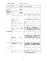
1. Tighten cylinder head and bolts (inc suspension). Tighten torque please refer to corresponding
instruction. Tighten torques please refer to corresponding instructions.
2. Check valve clearance.
3. Check lubricant level of final drive and clean ventilation plug.
4. Replace engine oil
、
axle oil and oil filter element.
5. Replace hydraulic oil and oil tank filter of power steering hydraulic system.
Summary of Contents for XMQ6127 series
Page 18: ...Operation Instruction CI 1 Figure 17 Set MotPPR Figure 18 Clear Trip A Figure 19 Clear Trip B...
Page 32: ...Operation Instruction P A 1 2 Control panel operation...
Page 33: ...Operation Instruction P A 1...
Page 34: ...Operation Instruction P A 1...
Page 35: ...Operation Instruction P A 1...
Page 36: ...Operation Instruction P A 1...
Page 41: ...Operation Instruction 0 G 1 1 1 2 2 Pushbutton Settings...
Page 42: ...Operation Instruction 0 G 1 1 2 Starting the Engine 1 3 Selecting the Gear...
Page 43: ...Operation Instruction 0 G 1 1 4 Setting Off 1 5 Driving Ranges...
Page 44: ...Operation Instruction 0 G 1 1 5 1 Downhill Travel 1 5 2 Downhill Travel 1 5 3 Kickdown...
Page 46: ...Operation Instruction 0 G 1 1 6 Stopping Parking...
Page 51: ...Operation Instruction 0 G 1 1 11 1 Limp Home Mode 1 12 Auxiliary Control Unit...
Page 52: ...Operation Instruction 0 G 1 1 12 1 Operating Instructions for the Auxiliary Control Unit...
Page 53: ...Operation Instruction 0 AB 1 WABCO ABS BASIC INTRODUCTION...
Page 54: ...Operation Instruction 0 AB 1...
Page 55: ...Operation Instruction 0 AB 1...
Page 56: ...Operation Instruction 0 AB 1...
Page 57: ...Operation Instruction 0 AB 1...
Page 58: ...Operation Instruction 0 EC 1 ECAS System Introduction 1 System introduction...
Page 59: ...Operation Instruction 0 EC 1 3 System function...
Page 60: ...Operation Instruction 0 EC 1...
Page 77: ...Operation Instruction 0 E 1 CAN bus module...
Page 158: ...Appendix A 4 Air braking schematic diagram...
Page 159: ...A 5 Electric schematic diagram of the complete vehicle 1...
Page 160: ...A 6 Electric schematic diagram of the complete vehicle 2...
Page 161: ...A 7 Electric schematic diagram of the complete vehicle 3...
Page 162: ...A 8 Electric schematic diagram of the complete vehicle 4...


