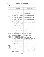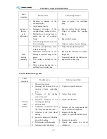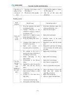
Maintenance and service
M-25
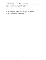
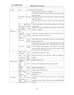
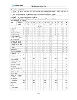
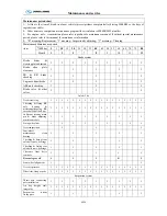
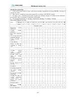
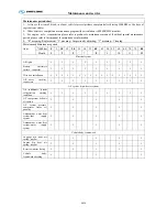
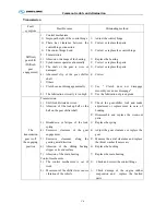
Maintenance period chart
1
、
1st line is the item of break-in of new vehicle (prescript items completed after driving 5000KM or the days of
registration vehicle)
2
、
Other items are compulsion maintenance program (the circulation is 80000KM/12 months)
3
、
For engine
、
axle
、
transmission please refer to producer’s maintenance manual, if without special maintenance
period, please refer to this manual for maintenance information.
4
、
“R” meaning: Replacement ; “I” meaning
:
Inspection & adjusting; “C” meaning
:
Cleaning
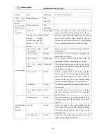
Maintenance
item
Maintenance period
*1000km
5
5
10
15
20
25 30 35
40
45 50 55
60 65 70 75
80
Month
1
3
5
7
8
9
10 11
12
Clutch
(
not applicable
)
Release or meshing if
not smoothly
I I I I I I
I
I
I I
I
I
I I I I
I
Oil pipe system
I
I
I
I
I
I
I
I
I
I
I
I
I
I
I
I
I
Clutch
plate
abrasion
I I I I I I
I
I
I I
I
I
I I I I
I
Free stroke of clutch
pedal
I I I I
I I
I I I
Clutch
oil
I I I I
I I
I I R
Clutch cylinder &
stroke
I I I I
I I
I I I
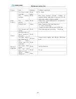
Transmission
Transmission if not
leaking oil
I I I I I I
I
I
I I
I
I
I I I I
I
Selector
mechanism
I I I I I I
I
I
I I
I
I
I I I I
I
Lubricant
oil
I I I I
I I
R I I
Venthole
C
I I I C I
I
I
C I
I
I
C I I I
C
Propeller shaft
Drive shaft connecting
parts
I I I I I I
I
I
I I
I
I
I I I I
I
Add lubricating oil in
drive shaft
I I I I I I
I
I
I I
I
I
I I I I
I
Universal joint cross
& bearing
I I I I
I I
I I I
Fixing
the
bolt
I I I I
I I
I I I
Middle bearing
bracket & clearance
I I I I I
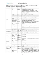
Brake system
Brake pedal free
stroke adjustment
I I I I I I
I
I
I I
I
I
I I I I
I
Driving brake
,
parking brake
I I I I I I
I
I
I I
I
I
I I I I
I
Brake pipe &
connector seal
I I I I I I
I
I
I I
I
I
I I I I
I
Air
dryer
I I I I I I
I
I
R I
I
I
I I I I
R
Brake
air
pressure
I I I I I I
I
I
I I
I
I
I I I I
I
ABS system checking
I
I
I
I
I
I
I
I
I
I
I
I
I
I
I
I
I
Brake
board
fixing
I I I I
I I
I I I
Retarder
C
C C C
C C
C C C
Summary of Contents for XMQ6127 series
Page 18: ...Operation Instruction CI 1 Figure 17 Set MotPPR Figure 18 Clear Trip A Figure 19 Clear Trip B...
Page 32: ...Operation Instruction P A 1 2 Control panel operation...
Page 33: ...Operation Instruction P A 1...
Page 34: ...Operation Instruction P A 1...
Page 35: ...Operation Instruction P A 1...
Page 36: ...Operation Instruction P A 1...
Page 41: ...Operation Instruction 0 G 1 1 1 2 2 Pushbutton Settings...
Page 42: ...Operation Instruction 0 G 1 1 2 Starting the Engine 1 3 Selecting the Gear...
Page 43: ...Operation Instruction 0 G 1 1 4 Setting Off 1 5 Driving Ranges...
Page 44: ...Operation Instruction 0 G 1 1 5 1 Downhill Travel 1 5 2 Downhill Travel 1 5 3 Kickdown...
Page 46: ...Operation Instruction 0 G 1 1 6 Stopping Parking...
Page 51: ...Operation Instruction 0 G 1 1 11 1 Limp Home Mode 1 12 Auxiliary Control Unit...
Page 52: ...Operation Instruction 0 G 1 1 12 1 Operating Instructions for the Auxiliary Control Unit...
Page 53: ...Operation Instruction 0 AB 1 WABCO ABS BASIC INTRODUCTION...
Page 54: ...Operation Instruction 0 AB 1...
Page 55: ...Operation Instruction 0 AB 1...
Page 56: ...Operation Instruction 0 AB 1...
Page 57: ...Operation Instruction 0 AB 1...
Page 58: ...Operation Instruction 0 EC 1 ECAS System Introduction 1 System introduction...
Page 59: ...Operation Instruction 0 EC 1 3 System function...
Page 60: ...Operation Instruction 0 EC 1...
Page 77: ...Operation Instruction 0 E 1 CAN bus module...
Page 158: ...Appendix A 4 Air braking schematic diagram...
Page 159: ...A 5 Electric schematic diagram of the complete vehicle 1...
Page 160: ...A 6 Electric schematic diagram of the complete vehicle 2...
Page 161: ...A 7 Electric schematic diagram of the complete vehicle 3...
Page 162: ...A 8 Electric schematic diagram of the complete vehicle 4...

