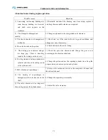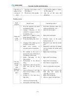
Common trouble and elimination
C-9
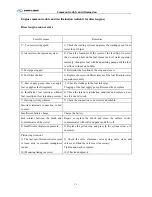
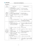
Transmission
Fault
symptom
Possible cause
Eliminating method
Difficult
gear shift
(Difficult
gear
engagement)
1.
Control mechanism
1)
Improper height of the control hinge
2)
There has clearance between the
control hinge connection
3)
The control hinge bend
2.
Transmission
1)
Abrasion or damage of the bearing
2)
Synchronizer operates abnormally
3)
The shaft or the gear is wore or
damaged
4)
Abnormal slip of the gear shifter
shaft
3.
Others
1)
Clutch can not disengage normally
2)
The lubrication viscosity is too high
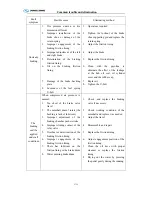
1
)
Adjust the control hinge
2
)
Correct or replace the parts
3
)
Correct or replace the control hinge
1
)
Replace the bearing
2
)
Correct or replace the parts
3
)
Correct or replace the parts
4
)
Correct
1
)
See " Clutch does not disengage
smoothly or can not disengage "
2
)
Use the lubrication of given grade
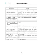
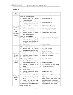
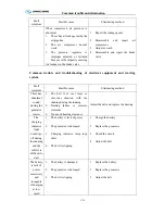
The
transmission
gear is off
the engaging
position
Transmission
1)
Shift fork distorted or worn
2)
Abrasion of lthe lockup ball or the
ball on the gear shifter shaft
3)
Breakdown or fatigue of the lock
spring
4)
Excessive clearance of the gear
engagement
5)
Excessive clearance along the
gearing axial direction
6)
Abrasion of the sliding bearing
slipper or its end surface
7)
Abrasion of the main bearing
Control mechanism
1)
The control mechanism is out of
work
2)
Movement of the shifter lever causes
vibration of the vehicle
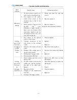
1
)
Check the gear-shifter fork and make
adjustment or replacement in case of
bending
2
)
Disassemble and replace the worn-out
parts
3
)
Replace the spring
4
)
Adjust the gear clearance or replace the
gear
5
)
Measure the axial clearance and replace
the thrust washer if necessary
6
)
Replace the bushing
7
)
Replace the main bearing
1)
Check and correct the control hinge
2)
Check damage of the engine rubber
suspension and replace the faulted
parts
Summary of Contents for XMQ6127 series
Page 18: ...Operation Instruction CI 1 Figure 17 Set MotPPR Figure 18 Clear Trip A Figure 19 Clear Trip B...
Page 32: ...Operation Instruction P A 1 2 Control panel operation...
Page 33: ...Operation Instruction P A 1...
Page 34: ...Operation Instruction P A 1...
Page 35: ...Operation Instruction P A 1...
Page 36: ...Operation Instruction P A 1...
Page 41: ...Operation Instruction 0 G 1 1 1 2 2 Pushbutton Settings...
Page 42: ...Operation Instruction 0 G 1 1 2 Starting the Engine 1 3 Selecting the Gear...
Page 43: ...Operation Instruction 0 G 1 1 4 Setting Off 1 5 Driving Ranges...
Page 44: ...Operation Instruction 0 G 1 1 5 1 Downhill Travel 1 5 2 Downhill Travel 1 5 3 Kickdown...
Page 46: ...Operation Instruction 0 G 1 1 6 Stopping Parking...
Page 51: ...Operation Instruction 0 G 1 1 11 1 Limp Home Mode 1 12 Auxiliary Control Unit...
Page 52: ...Operation Instruction 0 G 1 1 12 1 Operating Instructions for the Auxiliary Control Unit...
Page 53: ...Operation Instruction 0 AB 1 WABCO ABS BASIC INTRODUCTION...
Page 54: ...Operation Instruction 0 AB 1...
Page 55: ...Operation Instruction 0 AB 1...
Page 56: ...Operation Instruction 0 AB 1...
Page 57: ...Operation Instruction 0 AB 1...
Page 58: ...Operation Instruction 0 EC 1 ECAS System Introduction 1 System introduction...
Page 59: ...Operation Instruction 0 EC 1 3 System function...
Page 60: ...Operation Instruction 0 EC 1...
Page 77: ...Operation Instruction 0 E 1 CAN bus module...
Page 158: ...Appendix A 4 Air braking schematic diagram...
Page 159: ...A 5 Electric schematic diagram of the complete vehicle 1...
Page 160: ...A 6 Electric schematic diagram of the complete vehicle 2...
Page 161: ...A 7 Electric schematic diagram of the complete vehicle 3...
Page 162: ...A 8 Electric schematic diagram of the complete vehicle 4...

