1
Calibration Procedures
42
Keysight E3632A Service Guide
Calibration Count
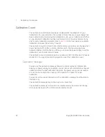
The calibration count feature provides an independent “serialization” of your
calibrations. You can determine the number of times that your power supply has
been calibrated. By monitoring the calibration count, you can determine whether
an unauthorized calibration has been performed. Since the value increments by
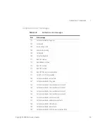
one for each calibration parameter (see
on the next page), a complete
calibration increases the value by 5 counts.
The calibration count is stored in non-volatile memory and does not change when
power has been off or after a remote interface reset. Your power supply was
calibrated before it left the factory. When you receive the power supply, read the
calibration count to determine its value.
The calibration count increments up to a maximum of 32,767 after which it wraps
around to 0. No way is provided to program or reset the calibration count.
Calibration Message
You can use the calibration message feature to record calibration information
about your power supply. For example, you can store such information as the last
calibration date, the next calibration due date, the power supply’s serial number,
or even the name and phone number of the person to contact for a new
calibration.
You can record and read information in the calibration message from the remote
interface only.
The calibration message may contain up to 40 characters.
The calibration message is stored in non-volatile memory and does not change
when power has been off or after a remote interface reset.
Summary of Contents for E3632A
Page 1: ...Keysight E3632A DC Power Supply Service Guide ...
Page 12: ...Keysight E3631A Service Guide 14 THIS PAGE HAS BEEN INTENTIONALLY LEFT BLANK ...
Page 14: ...16 Keysight E3631A Service Guide THIS PAGE HAS BEEN INTENTIONALLY LEFT BLANK ...
Page 16: ...18 Keysight E3631A Service Guide THIS PAGE HAS BEEN INTENTIONALLY LEFT BLANK ...
Page 68: ...2 Service 70 Keysight E3632A Service Guide ...
Page 70: ...72 Keysight E3632A Service Guide Component locator diagram for the front panel top ...


