


Keysight E1412A Digital Multimeter User Guide
cxxxvii
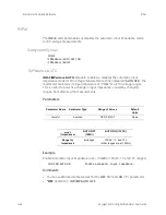
OUTPut
Multimeter Command Reference
OUTPut
The
OUTPut
command subsystem enables you to route the multimeter's
voltmeter complete
signal to the VXIbus TTL trigger lines.
Subsystem Syntax
OUTPut
:TTLTrg<
n
>[:STATe] <
mode
>
:TTLTrg<
n
>[:STATe]?
:TTLTrg[:STATe]
OUTPut:TTLTrg<
n
>[:STATe] <
mode
>
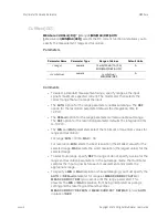
enables or disables routing of the
voltmeter complete
signal to the specified VXIbus trigger line (TTLTrg0 through
TTLTrg7) on the backplane P2 connector.
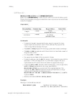
Parameters
Comments
–
You can substitute decimal values for the
OFF
(“
0
”) and
ON
(“
1
”)
parameters.
–
The
voltmeter complete
signal is always routed to the multimeter's front
panel “VM Complete” BNC connector. When enabled (
ON
), the
OUTPut
command also routes
voltmeter complete
to the specified trigger line on
connector P2. When disabled (
OFF
),
voltmeter complete
is routed only to
the multimeter's front panel connector.
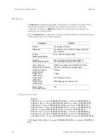
–
The multimeter generates the
voltmeter complete
signal after it has
sampled the input for each reading. The length of time this low-going TTL
signal is true (low) depends on the aperture time and on the autozero
mode as shown below.
Parameter Name Parameter Type
Range of Values
Default
Units
<
n
>
discrete
0|1|2|3|4|5|6|7
none
<
mode
>
boolean
OFF|0|ON|1
none
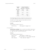
Aperture
Time
Voltmeter Complete Low
Autozero ON
Autozero OFF
320ms (50Hz)
350ms
350
s
267ms (60Hz)
370
s
370
s
Summary of Contents for E1412A
Page 1: ...Keysight E1412A 6 1 2 Digit Multimeter User Manual and SCPI Programming Guide 75000 Series C ...
Page 2: ......
Page 6: ...vi ...
Page 18: ...xviii Keysight E1412A Multimeter User Guide ...
Page 242: ......