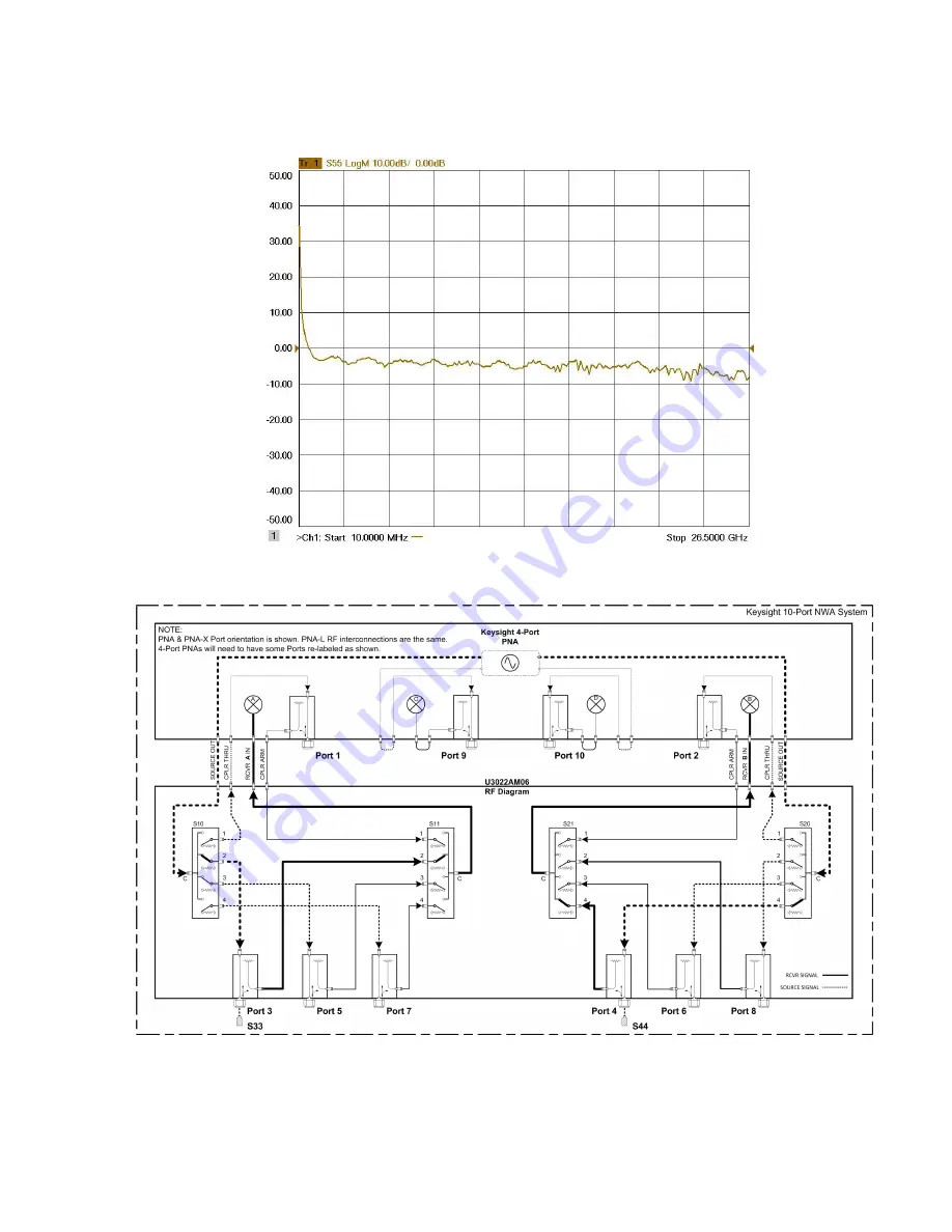
Figure 31
U3022AM06
System Operational Checks
Typical Reflection Response Ports 3-8
Figure 32
Reflection Response Signal Path Diagram Ports 3-8
42
Keysight U3022AM06 User's and Service Guide
Page 1: ...ice This document contains references to Agilent Technologies Agilent s former Test and Measurement business has become Keysight Technologies For more information go to www keysight com Use this manua...
Page 2: ...ware to U S government customers under its standard commercial license which is embodied in its End User License Agreement EULA a copy of which can be found at http www keysight com find sweu la The l...
Page 3: ...60002 25 Hardware Lock Link Installation U3021 60003 28 RF Interface Cable Connections U3021 60045 31 RF Interface Cable Connections U3021 60043 33 Cable Connection Procedure 33 RF Interface Cable Con...
Page 4: ...ting the Test Port Paths with Address and Data for Option 129 62 Control Lines 64 Internal Voltage Supply Configuration 66 External Voltage Supply Configuration 67 Equipment Required 70 Verification L...
Page 5: ...Cleaning Precautions 97 Electrostatic Discharge Protection 97 Regulatory and Instrument Markings Information 98 Instrument Markings 98 EMC Compliance 99 South Korea Class A EMC Declaration 99 Safety...
Page 6: ...Table of Contents...
Page 7: ...U3022AM06 Keysight U3022AM06 User s and Service Guide 7...
Page 8: ...U3022AM06 Introduction Introduction This document describes how to use and service the U3022AM06 Multiport Test Set Figure 1 U3022AM06 Test Set 8 Keysight U3022AM06 User s and Service Guide...
Page 9: ...U3022AM06 Introduction Figure 2 N5230A 4 Port PNA L with U3022AM06 Figure 3 E8362B 2 Port PNA with U3022AM06 Keysight U3022AM06 User s and Service Guide 9...
Page 10: ...U3022AM06 Introduction Figure 4 N5222A B or N5242A B 2 Port PNA X with U3022AM06 Figure 5 N5222A B or N5242A B 4 Port PNA X with U3022AM06 10 Keysight U3022AM06 User s and Service Guide...
Page 11: ...PNA and PNA X Network Analyzers will be referred to throughout this document as the PNA and PNA X The U3022AM06 will be referred to as the Test Set Verifying the Shipment Table 1 To verify the content...
Page 12: ...the measurement system to cover the full frequency range of the Test Set option listed above the network analyzer s frequency range should equal or exceed that of the Test Set PNA X Configuration Requ...
Page 13: ...loss measurements exhibiting a 0 1 dB uncertainty ripple residing on the measurement response is not uncommon Switch Configuration Command Speed When writing address and data values to the test set d...
Page 14: ...ware Lock link Kit Cable Kit Conn Type N5222A B Opt 401 417 or 419 PNA U3021PL3 442 U3021 60002 U3021 60047 SMA m me N5232A B Opt 416 PNA L U3021PL3 430 U3021 60001a U3021 60045 SMA m mc N5242A B Opt...
Page 15: ...fety Class I product provided with a protective earthing ground incorporated in the power cord The mains plug shall only be inserted into a socket outlet provided with a protective earth contact Any i...
Page 16: ...cabinet must be less than the maximum operating temperature of the instrument by 4 C for every 100 watts dissipated in the cabinet If the total power dissipated in the cabinet is greater than 800 watt...
Page 17: ...input power levels for the Analyzer access and test ports or to optimize the power levels in the receivers Damage and maximum levels are not necessarily the optimum level Table 6 Recommended Maximum P...
Page 18: ...Calibration Typical performance is based on 1 to 2 units performance Refer to Table 7 and Table 8 Table 7 Table 8 Frequency dB 300 kHz to 10 MHz1 1 N5230A C only 0 2 10 MHz to 4 GHz 3 4 GHz to 6 GHz...
Page 19: ...n Source or Receiver mode On the front panel S indicates Source test ports and R indicates Receiver test ports The switch is only a Standby switch not a AC line power switch The Active LED is on when...
Page 20: ...structure to ensure a common potential and reduce leakage current in a system Requires an English 1 4 20 thread nut 2950 0004 and lock washer 2190 0067 Connection to another Test Set The Test Set Int...
Page 21: ...ircuits from the mains supply before other parts of the instrument The front panel switch is only a standby switch and is not a LINE switch Alternatively an externally installed switch or circuit brea...
Page 22: ...voltage sources before being opened Locking the Test Set to the Analyzer 1 The lock link kit U3021 60001 includes the following 5023 9253 Lock link kit left 5022 2816 right 5022 2817 Test Set 5023 013...
Page 23: ...5 Remove the two upper standoffs from the rear panel on the Test Set 6 Install the left and right lock links onto the Test Set Figure 11 Install Rear Lock links to the Test Set Screws 0515 1619 T20 M...
Page 24: ...ng the spring loaded screws If the Analyzer s lock links are not aligned with the screw holes loosen the screws securing the lock links to the instrument slightly to align and tighten Figure 13 Lock L...
Page 25: ...sources before being opened Locking the Test Set to the Analyzer 1 The lock link kit U3021 60002 includes the following 5023 0132 Lock link kit left right and screws Analyzer 5023 2317 Screw T15 M3 5x...
Page 26: ...inks 5 Remove the top two standoffs from the rear panel on the Test Set 6 Install the left and right lock links onto the Test Set Figure 16 Install Lock link on Test Set Screws 0515 1619 T20 M4X0 7 25...
Page 27: ...to the Test Set s upper lock link using the spring loaded screws If the Analyzer s lock link are not aligned with the screw holes loosen the screws securing the lock link to the instrument slightly t...
Page 28: ...s before being opened Locking the Test Set to the Analyzer 1 The lock link kit U3021 60003 includes to interface the Test Set to the Analyzer 5023 0132 Lock links kit left right pair and screws Analyz...
Page 29: ...torx driver 6 Install the two rear lock links onto the Test Set Looking at the front panel the N5242 20130 is the right foot and the N5242 20131 is the left foot Two screws 0515 2317 are included with...
Page 30: ...to the Test Set s upper lock link using the spring loaded screws If the Analyzer s lock link are not aligned with the screw holes loosen the screws securing the lock link to the instrument slightly t...
Page 31: ...ables from the PNA L to the Test Set As you are connecting each cable torque to 8 in lb Refer to Table 9 and Figure 24 on page 32 Over torque will cause damage to the Test Set and may cause the connec...
Page 32: ...s 3 Add the front panel port labels from the cable kit U3021 60045 over the Analyzer s port numbers Port 2 over Port 4 U3022 80004 Port 9 over Port 2 U3022 80006 Port 10 over Port 3 U3022 80007 Refer...
Page 33: ...mper x1 remain on the front panel 2 Connect the RF interconnect cables from the PNA to the Test Set in the order listed As you are connecting each cable torque to 8 in lb Refer to Table 10 and Figure...
Page 34: ...3022 20116 Port 1 SOURCE OUT Ports 3 5 and 7 SOURCE IN 2 U3022 20117 Port 1 CPLR THRU Port 3 5 and 7 CPLR THRU 3 U3022 20118 Port 1 CPLR ARM Port 3 5 and 7 CPLR ARM 4 U3022 20119 Port 1 RCVR A IN Port...
Page 35: ...rence loop jumper x2 or x4 remain on the front panel 2 Connect the RF interconnect cables from the PNA or PNA X to the Test Set in the order listed As you are connecting each cable torque to 8 in lb T...
Page 36: ...46 or U3021 60047 Numeric Order RF Cables From PNA or PNA X To Test Set 1 U3042 20031 Port 1 SOURCE OUT Ports 3 5 and 7 SOURCE IN 2 U3042 20032 Port 1 CPLR THRU Port 3 5 and 7 CPLR THRU 3 U3042 20029...
Page 37: ...umper x2 or x4 remain on the front panel 2 Connect the RF interconnect cables from the PNA or PNA X to the Test Set in the order listed As you are connecting each cable torque to 8 in lb The longer st...
Page 38: ...m PNA X To Test Set 1 U3022 20160 Port 1 SOURCE OUT Ports 3 5 and 7 SOURCE IN 2 U3022 20161 Port 1 CPLR THRU Port 3 5 and 7 CPLR THRU 3 U3022 20162 Port 1 CPLR ARM Port 3 5 and 7 CPLR ARM 4 U3022 2016...
Page 39: ...on the rear panel similar to Figure 28 PNA or PNA X Test Set I O Cable Connection Interconnect Cable Verification 1 Perform the System Operational Checks on page 40 2 If the problem still exists perf...
Page 40: ...ncy range 10 MHz to 26 5 GHz or highest frequency Set the Analyzer to measure S11 Verify Results The trace ripple peak peak variation will be higher than when using an ECal Module due to variation in...
Page 41: ...Figure 29 U3022AM06 System Operational Checks Typical Reflection Response Ports 1 2 Figure 30 Reflection Response Signal Path Diagram Ports 1 2 Keysight U3022AM06 User s and Service Guide 41...
Page 42: ...Figure 31 U3022AM06 System Operational Checks Typical Reflection Response Ports 3 8 Figure 32 Reflection Response Signal Path Diagram Ports 3 8 42 Keysight U3022AM06 User s and Service Guide...
Page 43: ...igure 33 U3022AM06 System Operational Checks Reflection Response Signal Path Diagram Ports 5 6 Figure 34 Reflection Response Signal Path Diagram Ports 7 8 Keysight U3022AM06 User s and Service Guide 4...
Page 44: ...licized in parenthesis are menu paths for the B model analyzers Definitions for Specifications Specifications describe the warranted performance of calibrated instruments that have been stored for a m...
Page 45: ...pability To access the multiport application select Utility System Configure Multiport Capability OR Instrument Setup External Hardware Multiport Multiport Configuration 2 Select U3022AM06 8 or 10 Por...
Page 46: ...The Test Set will be displayed as External Test Set Control U3022AM06 External Test Set Control This menu will allow the physical Ports 1 thru 10 to be identified as any port for your convenience For...
Page 47: ...the port is the Receiver and the S LED indicates the port is the Source The B Model analyzer provides an S parameter selection using the keypad For example to select S25 MEAS MEAS Enter S Parameters...
Page 48: ...M06 Controlling the Test Set 10 Port New Trace Measure S11 S55 Figure 40 10 Port New Trace Measure S66 S1010 Use the scroll bar to select other s parameter measurements 48 Keysight U3022AM06 User s an...
Page 49: ...er to the Application Note 1373 1 and 1373 2 5988 5634EN and 5988 5635EN at http www keysight com In the search menu type Multiport and Balanced Selecting Balanced Measurements Receivers Tab Figure 42...
Page 50: ...nternal Hardware RF Path Config and in the drop down menu select Default OK Save this configuration as a User Preset by selecting Save UserPreset Save current state as User Preset Do not use the facto...
Page 51: ...esponse Cal Cal Sets Cal Kits Characterize ECals Calibrate at the end of the test port RF cables and any adapters that are used to connect the DUT This removes the effect on the measurement of the DUT...
Page 52: ...ing the Cal Wizard prompts and click Measure after each connection The electrical delay value may be shown in the dialog box after the last measurement click OK 6 At the Calibration Completed prompt s...
Page 53: ...alyzer s Help menu Rear Panel Tour and Interface Control A unique set of control data can be sent for each channel In addition a unique set of control data can be sent before the channel sweep starts...
Page 54: ...Interface Control If you are using an E8362B select Channel Interface Control in the drop down menu and select Enable Interface Control The analyzer includes the Interface Control application and rear...
Page 55: ...erface Control is disabled and NO data is sent To send data the individual interfaces must also be enabled Provides control of the Test Set I O Interface on the rear panel of the analyzer Used to cont...
Page 56: ...el begins sweeping The After Sweep Start data is sent after the last trace on the channel sweep is completed Specifies a wait time in milliseconds after all commands to all interfaces are sent Any pos...
Page 57: ...1 or in non standard measurement classes such as Scalar Mixer Converter Swept IMD Noise Figure Cold Source etc The user is required to manually input address and data using the Command Processor Conso...
Page 58: ...amples of the two control methods will be provided Method 1 Using GPIB SCPI Command Values This method is available while the system is in Multiport mode only The Test Set internal switch settings are...
Page 59: ...st Set Address and Data Values This method is available while the system is in Standalone mode only The address and data values for the Test Set can be found in the Address and Data Values section on...
Page 60: ...igure 53 on page 61 If the ports have the same address only one commands is needed Port 3 is the Source and Port 7 is the Receiver Source Port 3 address 0 data 1 and Receiver Port 7 address 0 data 48...
Page 61: ...Figure 53 U3022AM06 Address and Data Values Example Address and Data Port 3 and 7 Keysight U3022AM06 User s and Service Guide 61...
Page 62: ...oise Source Port Combinations for Ports 1 3 5 7 Data 0 0 Address Data 8 24 40 56 9 25 41 57 10 26 42 58 11 27 43 59 Source Port Receiver Port Source Port Receiver Port 1 1 1 1 3 3 3 3 3 1 7 5 3 1 7 5...
Page 63: ...le 3 Source Port 3 with Option 129 enabled and Receiver Port 7 address data value 0 57 from Table 15 on previous page As shown in Figure 54 below we used the Interface Control Mode to send 0 57 as a c...
Page 64: ...to 5 Vdc or an external DC power supply depending on how the connection to the control line is configured When using an external power supply a positive or negative voltage can be used Refer to Figure...
Page 65: ...n 14 5 Line 5 Control Line Output of the voltage from pin 13 or pin 14 6 Line 6 Control Line Output of the voltage from pin 13 or pin 14 7 Line 7 Control Line Output of the voltage from pin 13 or pin...
Page 66: ...gure 56 illustrates an example of the connection between the DUT and the Test Set using the internal DC power supply Connect pin 12 to pin 13 and pin 14 to pin 15 to provide the ground path Connect th...
Page 67: ...Test Set using an External Power Supply 1 Turn on the Test Set 2 Connect the DUT 3 Turn on the external power supply Turning On the Test Set using an External Power Supply 1 Turn off the Power Supply...
Page 68: ...he address value is always 112 Table 18 Test Set DUT Control Address and Data Logic Table Address Data Description Line Pin 112 0 ALL DUT Control Lines set to logic high or connected to Pin 13 1 8 112...
Page 69: ...lues Listed are two examples to illustrate this concept Refer to Figure 55 on page 65 shown with all lines logic high Example 1 To change lines 1 8 to equal logic Low all others logic high 1 Line 1 ad...
Page 70: ...st Set Table 19 Equipment Required Description Qty N4691A 3 5 mm ECal Module 10 MHz to 26 5 GHz Option 00F or M0F or N4691B 3 5 mm ECal Module 300 kHz to 26 5 GHz Option 00F or M0F or Mechanical cal k...
Page 71: ...ance exceed the operational verification limits A periodic calibration is not required The Operators Check should be performed after System Setup or if performance is in question An N Port calibration...
Page 72: ...Sets with these names 4 Verify that the analyzer is in Multiport mode See the bottom of the measurement window a If only four S Parameters are listed select Utility System Configure MultiportCapabili...
Page 73: ...dialog box Figure 58 1 Port Calibration 5 Continue to follow the prompts At the Calibration Completed dialog box select Save As User Calset type the name 999 1 Overwrite the Calset if it already exist...
Page 74: ...et Viewer 3 From the Cal Sets drop down menu select 999 1 and select Enable Select the Reflection Tracking x x where x x is the port being tested Ensure that the Enable and Error Terms check boxes are...
Page 75: ...C or N5230A C Figure 62 Typical Reflection Tracking with N5242A B Ports 1 2 Response from 10 MHz to 500 MHz is normal due to the PNA or PNA X couplers in comparison to the Test Set bridges The bridges...
Page 76: ...Figure 63 U3022AM06 Cal Kit Operational Check Typical Reflection Tracking Trace with N5242A B Ports 3 to 8 76 Keysight U3022AM06 User s and Service Guide...
Page 77: ...ormed with mechanical standards or an ECal module In order to perform this check the test port of the ECal module must connect directly to the test port being verified without adapters 1 Perform a 1 P...
Page 78: ...structions are for use by qualified personnel only To avoid electrical shock do not perform any servicing unless you are qualified to do so Special options are built to order so long lead times may be...
Page 79: ...U3022AM06 System Block Diagram System Block Diagram Figure 65 U3022AM06 Standard Configuration Keysight U3022AM06 User s and Service Guide 79...
Page 80: ...Figure 66 U3022AM06 System Block Diagram U3022AM06 Option 129 80 Keysight U3022AM06 User s and Service Guide...
Page 81: ...yzer Ports 1 thru 2 and Test Set ports paths 3 thru 8 Switch Paths S10 Source to Ports 1 3 5 and 7 S20 Source to Ports 2 4 6 and 8 S11 Receiver to Ports 1 3 5 and 7 S21 Receiver to Ports 2 4 6 and 8 S...
Page 82: ...the Test Set interface cable is connected and the Test Set is addressed by the network analyzer 2 Turn on the Test Set and the analyzer The rear panel Deck and Internal power supply fans should be op...
Page 83: ...connected properly Refer to Control Lines on page 64 b Verify that the rear panel DC voltage control adjustment can be set to 5 Vdc Refer to Figure 7 on page 20 d If the DC Indicator LEDs are not on s...
Page 84: ...port Mode 3 Using the Test Set I O Data command values to be given in the preceding procedure you will observe S21 response measurements RF Switching Path Test If you suspect an RF signal path problem...
Page 85: ...g Test Instructions table will be used to configure the RF switches for this testing After making your entry select OK to execute the command to return back for further entries select Interface Contro...
Page 86: ...re 70 on page 88 6 Rcvr Out to Port 5 0 32 P5 Cplr S11 7 0 48 P7 Cplr S11 Rcvr Out to Port 7 9 Source In to Port 4 16 1 P4 Cplr S20 Figure 68 on page 87 10 Source In to Port 6 16 2 P6 Cplr S20 11 Sour...
Page 87: ...Figure 68 U3022AM06 Troubleshooting the Test Set Source IN to Ports 3 8 Path Response Figure 69 Source IN to Cplr Thru Rcvr Out to Cplr Path Response Keysight U3022AM06 User s and Service Guide 87...
Page 88: ...Figure 70 U3022AM06 Troubleshooting the Test Set Rcvr Out to Ports 3 8 Path Response 88 Keysight U3022AM06 User s and Service Guide...
Page 89: ...Figure 71 U3022AM06 Wiring Diagram and Internal Views Test Set Diagram Wiring Diagram and Internal Views Keysight U3022AM06 User s and Service Guide 89...
Page 90: ...2AM06 Wiring Diagram and Internal Views Top View DUT Control Board S11 S10 S21 S20 RF Switch Switch Interface Board Power Supply LEDs Active LED Harness RF Couplers x6 90 Keysight U3022AM06 User s and...
Page 91: ...e 73 U3022AM06 Wiring Diagram and Internal Views Bottom View Power Supply Rear Panel Fan Fuse Assy S11 S10 S21 S20 RF Couplers x6 Screw Terminals for Supplies Keysight U3022AM06 User s and Service Gui...
Page 92: ...ring Diagram and Internal Views Top View Option 129 DUT Control Board S11 S16 S21 S20 RF Switch Switch Interface Board Power Supply LEDs Active LED Harness RF Couplers x6 S10 92 Keysight U3022AM06 Use...
Page 93: ...22AM06 Wiring Diagram and Internal Views Bottom View Option 129 Power Supply Rear Panel Fan Fuse Assy S11 S16 S21 S20 RF Couplers x6 Screw Terminals for Supplies S10 Keysight U3022AM06 User s and Serv...
Page 94: ...ed in the power cord The mains plug shall only be inserted in a socket outlet provided with a protective earth contact Any interruption of the protective conductor inside or outside of the product is...
Page 95: ...rious injury This product is designed for use in Installation Category II and Pollution Degree 2 Verify that the premise electrical voltage supply is within the range specified on the instrument When...
Page 96: ...user to dangerous voltages Disconnect the instrument from all voltage sources before opening No operator serviceable parts inside Refer servicing to qualified personnel To prevent electrical shock do...
Page 97: ...ion of fumes or vapors Electrostatic Discharge Protection Electrostatic discharge ESD can damage or destroy electronic components The product is shipped in materials that prevent damage from static an...
Page 98: ...ired by EU directives applicable to our product The CSA mark is a registered trademark of the CSA International This is a symbol of an Industrial Scientific and Medical Group 1 Class A product CISPR 1...
Page 99: ...n Low Voltage Directive Safety South Korean Class A EMC Declaration Information to the user If this instrument is equipped with a KC label it has been conformity assessed for use in business environme...
Page 100: ...ce or Repair IMPORTANT Keysight Technologies reserves the right to reformat or replace the internal hard disk drive in your analyzer as part of its repair This will erase all user information stored o...
Page 101: ...Keysight U3022AM06 User s and Service Guide 101...
Page 102: ...This information is subject to change without notice Keysight Technologies 2009 2019 Print Date August 2019 Supersedes November 2017 U3022 90006 www keysight com...