background image

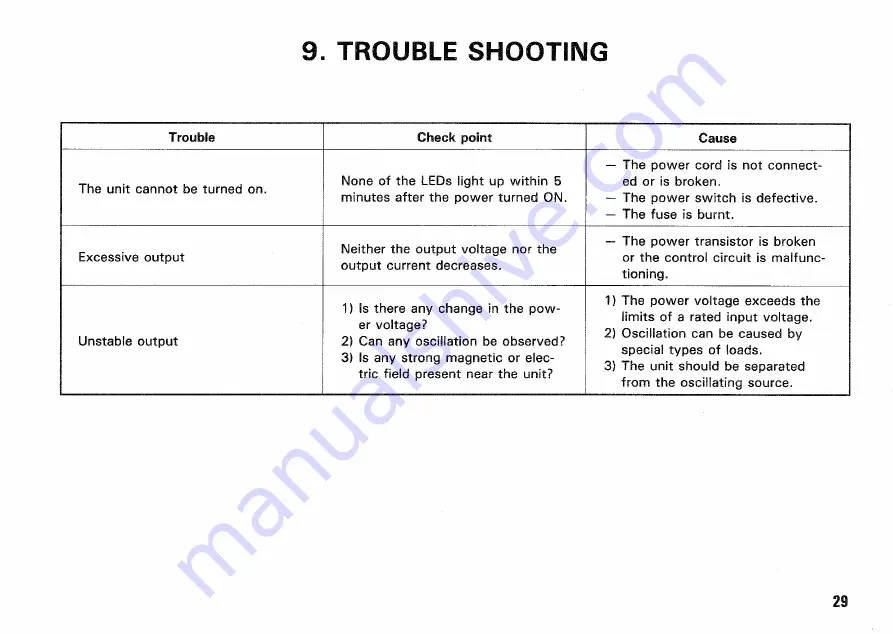
9. TROUBLE SHOOTING 

Trouble 

C h e c k point 

Cause 

T h e unit cannot be turned on. 

None of the  L E D s light up within 5 
minutes after the power turned  O N . 

—  T h e power cord is not connect-

ed or is broken. 

—  T h e power  s w i t c h is defective. 
—  T h e  f u s e is burnt. 

E x c e s s i v e output 

Neither the output voltage nor the 

output current decreases. 

—  T h e power transistor is broken 

or the control circuit is malfunc-
tioning. 

Unstable output 

1) Is there any change in the pow-

er voltage? 

2)  C a n any oscillation be observed? 
3) Is any strong magnetic or elec-

tric field present near the unit? 

1)  T h e power voltage  e x c e e d s the 

limits of a rated input voltage. 

2) Oscillation  c a n be  c a u s e d by 

special  t y p e s of loads. 

3)  T h e unit should be separated 

from the oscillating source. 

29 

Summary of Contents for PWR 18-2

Page 1: ... PRINTED IK PAN B63 0028 Q0 T 91 12 1110 9 8 7 6 5 4 3 2 1 90 12 1110 9 REGULATED DC POWER SUPPLY PWR18 2 PWR36 1 INSTRUCTION MANUAL Part of Power Supply Function KENWOOD CORPORATION KENWOOD ...

Page 2: ...equipment generates uses and can radiate radio frequency energy and if not installed and used in accordance with the instructions may cause harmful interference to radio communications However there is no guarantee that interference will not occur in a particular installation If this equipment does cause harmful interference to radio or television reception which can be determined by turning the e...

Page 3: ... are the first in their class with built in microcomputers making their multi functional capabilities second to none in the market Their dual tracking function is helping the series achieve the highest of reliability Moreover thier multi output is earning them a several fold lead over conventional single output power sup ply units making the PWR series most ideal for research and as pa power sourc...

Page 4: ... set to be fixed This prevents the current values from being altered by someone else while the user is o u t Protect function Prevents unexpected voltage and current from being output to an external application board This function is helpful when the preset key variable key and tracking key are pressed in the output operation mode Safety mechanism design Well designed heat sink provid ed for preve...

Page 5: ...1 40 mV of rated voltage 1 80 mV of rated voltag OUTPUT CURRENT Output current 0 to 2A 0 to 2A 0 to 1A 0 to 1A Setting resolution 10 mA Max output current 2 A 2 A M Dual tracking 0 to 2A 0 to 1A Tracking deviation 2 4 0 mA of rated current CONSTANT VOLTAGE CHARACTERISTICS Input fluctuation for surge of A C 10 1 mV 2 mV Load fluctuation for surge of 0 to 100 3 mV 2 mV Ripple noise rms 10 Hz to 1 MH...

Page 6: ...le noise rms 10 Hz to 1 MHz 2 mA rms typical Ripple peak p p 5 6 mA p p typical Temperature coefficient 300 ppm C typical VOLTMETER Display 3 1 2 digit LED max 19 99 V fixed range red LED max 19 99V 99 9V auto range red LED Accuracy output O N 23 C 5 C less than 8 0 RH 0 5 rdg 2 digit Low range 0 5 rdg 4 digit High range 0 5 rdg 1 digit AMPMETER Display 3 digit LED max 9 99 A fixed range red LED A...

Page 7: ...rents can be preset as desired Preset values can be easily checked Green LED lights up when ON Memory Several voltage and current presets can be stored Red LED lights when ON Key Lock Locks all functions as set All controls except POWER are disabled Red LED V A Several voltages and currents can be set Green LED Tracking and V A display selection 1 8 V tracking 1 8 V 1 8 V 3 6 V tracking 3 6 V 3 6 ...

Page 8: ...pprox 210 V A 165 W approx 190 V A 145 W INPUT V O L T A G E Voltage Frequency A C 100 V 1 0 120V 220V 2 4 0 V 1 0 max 250 V 50 60 Hz Internal switching possible DIMENSIONS AND WEIGHT Dimensions width 104 mm height 147 mm depth 330 mm Max dimensions width 109 mm height 167 mm depth 350 mm Weight approx 6 4 kg Accessory items 1 instruction manual 1 power supply cord 2 fuses 1 moduler cable Circuit ...

Page 9: ...tive and negative terminals or the positive and negative terminals with each other If a short is made use the machine after setting the output voltage to rather a low level If it is high the internal circuits may be damaged Keep it in mind This is a floating type power supply For normal use the provided shorting bar to connect the GND and COM termi nals In addition when connecting the short bar be...

Page 10: ...function pleased wait While the machine is in this state all control switches will be non functional If the system is turned off while the data 0 0 0 0 is displayed on the display panel the content of the backup memory may be destroyed It may cause an error Keep it in mind If the system is turned off due to operational errors or some other unavoidable errors for example power failure perform the o...

Page 11: ...everse voltage is generated 0 00 V is displayed and the display flashes Ammeter This indicates the output current value and the setting value of the positive and negative output current Rotary Encoder Knob for setting voltage and current values A rotary encoder knob is used to specify the output voltages and the output current limit values negative and positive If the V LED is turned on the voltag...

Page 12: ... lights when this key is pressed and the current limit value that is indi cated on the voltmeter can be varied of set by the rotary encoder When this key is pressed again the A LED goes off and the current limit value cannot be varied by the rotary encoder 18 Key OVERLOAD LED Green This key sets the output voltage or the positive current limit value and the LED indicates when this setting is possi...

Page 13: ...again the LED goes off and the tracking status is canceled The setting value remains at the same value as when the tracking is performed and is not reset to the original value VARIABLE Key VARIABLE LED Green This key varies the output setting value and the LED lights when this operation is possible Press this key to change the output setting value The LED lights to indicate that the output setting...

Page 14: ... is pressed when the MEMORY LED lights before the PRESET key is selected If the VARI ABLE key is pressed while the MEMORY LED is lit the VARIABLE LED lights up for about 3 seconds the ADDRESS NO used in the REMOTE mode is displayed on the voltmeter and ammeter displays Fore details see Sections 6 of this manual Operation Proce dure or the separate Remote Control Instruction Manual PRESET 1 2 3 key...

Page 15: ...Operating Procedure7 for a detailed explanation of the setting procedures KEY LOCK Switch KEY LOCK LED Red LOCAL Key LOCAL LED Green Orange This key turns the KEY LOCK setting ON and OFF and the LED lights to indicate the function status The KEY LOCK LED is OFF as the initial default setting af ter the power is first applied The LED lights when the KEY LOCK switch is turned ON When the KEY LOCK sw...

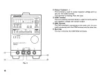
Page 16: ...floating from the case COIWS Terminal This is a common terminal which is used for both positive and negative voltage and current output GND Terminal The GND terminal is connected to the main unit It is nor mally connected with the COM terminal and the short bar Short Bar This bar connects the COM GND terminals Fig 4 16 ...

Page 17: ...he transistors Be careful not to touch it as it can be extremely hot from dissipating the heat from the components Remote Connector The connector used for input or output of remote signals when the machine is used with the remote control mode Be sure to use the connecting chord provided with the machine For details please see the separate Remote Con trol Instruction Manual Fig 5 17 ...

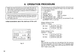
Page 18: ...ngs when the unit is powered for the first time after purchase or after it has not been used for a long period of time Display settings for the positive output Display settings for the negative output Note 1 After the first use of the unit the settings from the previous operation just before the power shut off are displayed Note that the OUTPUT mode is set to OFF and the OUTPUT PRO T E C T mode is...

Page 19: ... V 1 A respectively for the 36 1 model 2 When the VARIABLE LED is lit up orange F A S T mode and the Rotary Encoder knob is rotated slow ly the voltage current and delay time settings will change by the same increments as for the S L O W mode i e 10 mV 10 mA However if the knob is turned quickly in the F A S T mode the settings will change in increments of about double those in the S L O W mode Be...

Page 20: ... as shown in the Figure 8 Make sure that the OUTPUT LED is not lit 2 Turn the Rotary Encoder to set an arbitrary voltage value 3 Press the A KEY 6 and make sure that the A LED lights up 4 Turn the Rotary Encoder to set an arbitrary current limit value 5 Press the OUTPUT K E Y to obtain the output value en tered from the negative output terminal If the OUTPUT KEY is pressed ON both positive and neg...

Page 21: ...serial with a load are re quired to prevent the discharge if the products is used as a battery charger or a memory backup battery 6 3 Tracking Power Supply Procedure 1 Set the LEDs as shown is Figure 9 Be sure that the OUTPUT LED is not lit Figure 9 indicates the case where positive voltage level is used 2 Turn the Rotary Encoder to set an arbitrary positive voltage value 3 Press the A KEY and mak...

Page 22: ... for new voltage and current values 6 4 PRESET feature 1 The PRESET feature is used to store the actually value setting displayed value in one of the PRESET 1 2 3 KEYs 1 Set the LEDs as indicated in Figure 10 Always make sure that the OUTPUT LED is not lit 2 Set a positive voltage value by the Rotary Encoder 3 Press the A KEY and turn the Rotary Encoder to set a positive current limit value 4 Pres...

Page 23: ...ious status postive negative output values and each LED status before the MEMORY key is pressed as described in 2 will be restored 6 5 OUTPUT PROTECT Feature The unit is equipped with the VARIABLE KEY and PRESET KEYs 1 2 3 to change and set an output value Each of these 4 keys can change a setting value output value when it is pressed If a different key is pressed by mistake while the Unit is in o...

Page 24: ...ECT feature is started up Other wise the value of the incorrectly selected output setting key will be output 21 Follow the below procedure to make sure that the OUT PUT PROTECT feature is set OFF 1 Press the OUTPUT KEY as shown in Figure 1 1 to turn off its LED 2 Press the OUTPUT KEY to turn O N the output 3 Nothing can be changed at this point if the VARIABLE KEY is pressed 4 Press one of the key...

Page 25: ...celled 3 If the product is turned off with the K E Y LOCK mode a c t i v e the K E Y LOCK mode will be still effective after power is supplied to the product next time That is every key operation will be disabled in this case Keep it in mind If new key operations need to be performed set the K E Y LOCK switch to the OFF mode 6 7 Rotary Encoder lock procedures If the selected V K E Y or A KEY is pr...

Page 26: ...7 APPLICATIONS 26 Usage for homopolar double output I I L I 2 I 2A M a x P W R I 8 2 I A M a x P W R 3 6 l Usage for serial output Serial Output Usage for complimentary output ...

Page 27: ...e unit remove the screws on the top To change the rated input voltage change the rated values of and sides of the unit and lift the case upwards the power transformer and fuse inside the unit as described in the following section 2 Illustration Illustration Fig 14 Fig 15 POWER switch F U S E ...

Page 28: ... a rated fuse that corresponds to the new power voltage see the table Be sure to disconnect the power cord from the A C out let before replacing the power voltage or the fuse Table Rated fuses Model 100V 120V 220V 240V PWR18 2 2A TL 2A TL 1 5A 1 5A PWR36 1 2A TL 2A TL 1 5A 1 5A TL Time Lag fuse Fuse Fig 17 28 ...

Page 29: ...the output voltage nor the output current decreases The power transistor is broken or the control circuit is malfunc tioning Unstable output 1 Is there any change in the pow er voltage 2 Can any oscillation be observed 3 Is any strong magnetic or elec tric field present near the unit 1 The power voltage exceeds the limits of a rated input voltage 2 Oscillation can be caused by special types of loa...

Page 30: ...10 EXTERNAL DIMENSIONS FIGURE Fig 18 Fig 19 30 ...

Page 31: ...Fig 20 Fig 21 Dimentlons of the PWR36 1 are Identical 31 ...

Page 32: ...A product of KENWOOD C O R P O R A T E 17 5 2 chome Shibuya Shibuya ku Tokyo 150 J K an ...

Reviews: