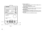
Fig. 4
standby mode w h e n the setting values in the P R E S E T k e y
© are recorded.
If this key is pressed w h e n the O U T P U T key © is set O F F ,
the M E M O R Y L E D lights to indicate that the preset opera-
tion c a n be'-performed. --
T h e setting value is stored for the selected key number by
setting the voltage and current setting value by the V - k e y
® , A - k e y ® or rotary encoder © and then selecting any
one of the P R E S E T k e y s ( 1 , 2 , and 3 ) . If this key is pressed
again the M E M O R Y LED goes off to indicate that the preset
s t a t u s is canceled.
T h e condition that w a s determined by the previous value
setting is restored if this key is pressed w h e n the M E M O R Y
LED lights (before the P R E S E T key is selected). If the V A R I -
A B L E key @ is pressed while the M E M O R Y L E D is lit, the
V A R I A B L E LED lights up for about 3 seconds, the A D D R E S S
NO. used in the R E M O T E mode is displayed on the voltmeter
@ and ammeter © displays.
Fore details, see Sections 6 of this manual ("Operation Proce-
d u r e " ) , or the separate Remote Control Instruction Manual.
@ PRESET ( 1 , 2 , 3) key / PRESET LED ( 1 , 2 , 3) (Green)
The output condition settings are stored in a key before oper-
ation and the LED lights in the corresponding keys w h e n the
settings are read.
Three t y p e s of output conditions within the standard range
can be set and stored a s desired.
T h e s e k e y s have t w o operations method. If the P R E S E T 1
key is pressed, the P R E S E T 1 LED lights. The following oper-
ations c a n be performed.
14


