UX-Z7MDR
(No.22042)1-51
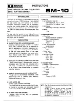
4.10 LB1641 (IC402) : DC Motor driver
• Pin layout
• Truth table
4.11 BD7910FV-X (IC450) : Pre driver
• Block diagram
• Pin function
1
2
3
4
5
6
7
8
9
10
GND
OUT1
P1
VZ
IN1
IN2
VCC1
VCC2
P2
OUT2
Input
Output
Mode
IN1
IN2
OUT1
OUT2
0
0
0
0
Brake
1
0
1
0
CLOCKWISE
0
1
0
1
COUNTER-CLOCKWISE
1
1
0
0
Brake
Pin No.
Symbol
I/O
Function
1
Vreg IN
I
Regulator input and regulator power supply
2
Reg GN
-
Regulator GND
3
NC
-
Non connect
4
VG
I
Voltage input for power MOS drive
5
SVCC
O
EFM high level output voltage
6
PDGND
-
Pre-driver GND
7
EFM
I
EFM signal input
8
MUTE
I
Mute control (Low active)
9
NC
O
Non conncet
10
NC
O
Non connect
11
NC
-
Non connect
12
VOD2
O
Sync.output (Lower power MOS,drain)
13
VSS
-
Hbridge GND (Lower power MOS,source)
14
VOD1
O
Sync.output (Lower power MOS,drain)
15
VOS1
O
Source output (Upper power MOS,source)
16
VDD
-
H bridge power supply terminal(Upper power MOSsource)
17
VOS2
O
Source output (Upper power MOSsource)
18
Reg DRV
O
External PNP drive output for regulator
19
Reg OUT
O
Reglator output (Emitter follower output)
20
Reg NF
-
Regulator feedbaack terminal
20 19 18 17 16 15 14 13 12 11
1 2 3 4 5 6 7 8 9 10
Vregin
VG
SVcc
Pre driver
EFM
Mute
- +
- +