background image

147

134

16

137

135

123

133

116

113

113, 116

135

135

134

134

132

134

134

134

134

Needle 

thread 

clamp 

failure

Bobbin 

thread at 

the start 

of sewing 

is drawn 

up on the 

cloth.

Knife to cut

needle 

thread is 

dull.

Interference 

of wiper 

with needle

Phenomenon

Bird’s nest prevention (cB) type

1

 Improper wiper position.

2

 Air pressure drop.

3

 Dust bag becomes excessively filled with 

waste thread.

4

 Thread trimmer or wiper operates when 

needle does not enter the cloth.

5

 Needle thread length is too short.

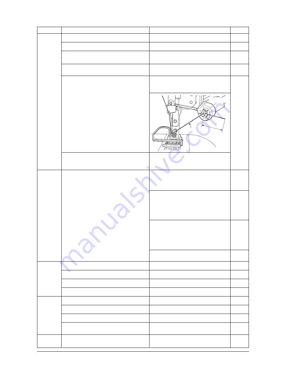
  Thread does not reach the clamp head.

6

 Uneven length of left and right needle threads

  (Thread which is not stretched such as 

cotton thread or the like is used.)

Adjust the wiper to the proper position.

Set the air pressure to 0.6Mpa.
Remove waste thread from the dust bag.

Operate thread trimmer or wiper on the 

cloth.
Perform pre-tension adjustment and lengthen 

needle thread. (Adjust the length from the 

clamp head to approximately 20 to 35 mm.)

See page

Cause

Corrective measure

Step 1 :

Increase the drawing amount of needle 

thread  and  increase  needle  thread 

remaining amount at the start of sewing.
Step 2 :

Make tension release SOL (solenoid) actuate at 

the start of sewing to perform tension release 

and increase the thread remaining amount. (Input 

the number of stitches of thread release at the 

start of sewing with function setting No.100.)
Step 3 :

Make the thread drawing device actuate 

again after completion of needle thread 

clamp  to  perform  tension  release  and 

increase the thread remaining amount.

(Set function setting No.18 to 2.)
Step 4 :

Make all step items (1 + 2 + 3) function.
Replace the knife with a new one.

Adjust the position to the proper one.

Change the thread count.

Change to the normal feed.

Adjust the UP stop position.

Re-adjust the locus of the wiper.

Re-adjust the position of the wiper.

Re-adjust the position of the wiper.

Replace  the  presser  with  the  general 

presser (presser without knife).

Bobbin  thread  is  taken  up  on  the  cloth  by 

needle thread at 1st stitch at the start of sewing 

since needle thread remaining amount after 

completion of needle thread clamp is small.

20 to 35 mm

Needle thread

clamp head

Change the kind of thread.

1

 Worn-out of needle thread cutting knife.

2

 Improper installing position of the knife.

3

 Thick thread is used.

4

 Start of sewing is set to the reverse feed.

1

 Improper UP stop position.

2

 Improper wiper locus.

3

 Improper wiper position.

4

 Length of needle tip is longer than that of the 

standard delivery needle.

1

 Needle thread enters the needle thread 

cutting groove of the presser.

Needle thread 

is cut during 

sewing.

Summary of Contents for LZ-2290A-SR/IP-110D/SC-916

Page 1: ...ENGLISH LZ 2290A SR IP 110D SC 916 Instruction Manual CompactFlash TM is the registered trademark of SanDisk Corporation U S A ...

Page 2: ...1 6 T stitch right 62 7 Pattern 1 64 8 Pattern 2 fagoting 65 9 Pattern 3 67 10 Pattern 4 69 6 7 Setting of the number of rotations 71 6 8 Reverse feed stitching 71 1 Standard condensation 72 2 2 point condensation 74 3 Condensation custom 75 4 Comparision table of the reverse stitch of each shape 76 6 9 Selection of the kind of stitching 77 1 Overlapped stitching 77 2 Programmed stitching 78 6 10 ...

Page 3: ... device 133 8 13 Adjusting the bird s nest prevention CB type wiper 134 8 14 Replacing procedure of the bird s nest prevention CB type presser knife 135 9 MAINTENANCE 136 9 1 Replacing the power fuse 136 9 2 Adjusting the contrast of the operation panel display 137 9 3 Draining Bird s nest prevention CB type only 137 9 4 Cleaning the dust bag Bird s nest prevention CB type only 137 9 5 Cleaning th...

Page 4: ...tch 9 Power switch 6 Mirror inversion switch 3 Thread take up cover 0 Hand switch 7 Reverse feed control lever 4 Finger guard 1 Control panel 5 Thread tension controller Rotary tension 2 Bobbin winder 6 Electrical box 3 Tension controller No 1 7 Pedal Pre tension 4 Thread stand 4 3 2 2 1 3 4 5 o q t 0 i y u 6 7 ...

Page 5: ...ormal reverse feed Stitch pattern 14 kinds 20 patterns Needle SCHMETZ 438 75 Needle at the time of delivery Oil used JUKI New Defrix Oil No 1 Thread trimmer With Feed method Standard feed Computer controlled system Wiper method Front sweeping method Side sweeping method Thread clamp method Air clamp method Noise Equivalent continuous emission sound pressure level LpA at the workstation A weighted ...

Page 6: ...igzag stitch 4 4 step zigzag stitch 6 Scallop right Standard scallop 24 Crescent scallop Equal width scallop Equal width scallop 12 Scallop left Standard scallop 24 Crescent scallop Equal width scallop Equal width scallop 12 Blind stitch right a 2 a Blind stitch left a Custom pattern 500 T stitch left 3 T stitch right Pattern 1 6 Pattern 2 fagoting Pattern 3 Pattern 4 ...

Page 7: ...stitches Standard scallop Crescent scallop Equal width scallop Equal width scallop Zigzag width 4 0 8 0 6 0 8 0 8 0 Normal feed amount 2 0 1 5 1 0 1 0 0 5 0 8 Reverse feed amount 0 0 0 0 0 0 0 0 0 0 0 0 Number of stitches Related input P 31 54 55 P 32 54 55 P 32 54 55 P 32 54 55 P 32 33 56 57 58 101 102 P 32 33 56 57 58 101 102 Related mechanical adjustment P 126 P 126 Remarks ...

Page 8: ...2 1 2 0 0 0 0 0 0 0 2 0 2 4 2 0 4 P 34 59 P 45 60 80 81 82 83 98 99 101 102 P 35 36 37 38 61 62 63 P 37 38 64 65 P 39 40 65 66 67 P 41 42 67 68 P 43 44 69 70 P 125 There are cases where the stitch shapes are not stabilized in case of some patterns which frequently repeat normal and reverse feed stitching Use the machine at the sewing speed of approximately 2 000 sti min ...

Page 9: ...it the machine head to table rubber hinge 8 before placing the machine head on cushions 3 on the four corners 5 Attach head support rod 6 to the machine table 4 INSTALLATION 4 1 Installation of the sewing machine head WARNING Perform the installation of the sewing machine by the technical personnel who have been trained To prevent personal injury ask our dealer or the electrician for electric wiri...

Page 10: ...nsert knee lifter into attaching hole 2 and tighten it with bolt 3 Adjust the position of knee lifter pad 1 to a convenient place For the reference dimension the position is 220 mm from the bottom face of table In case of the machine with AK device knee lifter pad 1 is optional Part No 22934251 4 3 Attaching the knee lifter Remove needle bar stopper 1 for transportation Keep the needle bar stopper...

Page 11: ...to 5 brown cord to 2 and sky blue cord to 3 with screws 3 Connecting the power cable supplied as accessories In case of 3 phase power cable Put power cable from hole B of the power switch and securely fix green yellow cord to 9 white cord to 6 black cord to 7 and red cord to 8 with screws In case of single phase power cable Put power cable from hole B of the power switch and securely fix green yel...

Page 12: ...rear cover opened A C B D 4 8 Connecting the cords WARNING To prevent personal injury caused by abrupt start of the sewing machine carry out the work after turning OFF the power switch and a lapse of 5 minutes or more To prevent damage of device caused by maloperation and wrong specifications be sure to connect all the corresponding connectors to the specified places To prevent personal injury cau...

Page 13: ...l box through front cover through hole B and pass it through cord clamp b as illustrated and tighten it with screw at the position 2 in the illustration 6 Insert white square connector 9P black cord 3 coming from the machine head inside the electrical box through front cover through hole B and insert it into connector CN38 4 of the circuit board attached to the front cover 7 Insert white connector...

Page 14: ...he electrical box through front cover through hole B pass it through cord clamps a c d and g and insert it into connector CN53 4 Close cord clamps a c and d 12 Insert white connector 6P cords 5 coming from the machine head inside the electrical box through front cover through hole B pass it through cord clamps e and j and insert it into connector CN54 6 13 1 Insert white connector 10P cord 9 and b...

Page 15: ... electrical box through front cover through hole B pass it through cord clamps e f h and j and insert the black square 10P into connector CN72 2 15 Insert black connector 4P cord 3 coming from the machine head inside the electrical box through front cover through hole B pass it through cord clamps e f h and j and insert the black 4P into connector CN73 4 16 Close cord clamps e f and j e f 1 2 h 3 ...

Page 16: ...ront cover through hole B coming from the foot pedal for standing work pass it through cord clamps a and c and insert it into connector CN32 0 20 Connect white connector 2P of cord 1 supplied as accessories to which red connector 2P and white connector 2P are attached to white connector 2P 2 of under cover of the machine head Fix omega lock 3 supplied as accessories with the neighboring cords and ...

Page 17: ...edium speed will be easier 5 22 Install core clamp 5 supplied as accessories at the position as shown in the figure For CE territory 1 2 3 A B C B 2 A 1 When the insertion of the connector is completed lock the cord clamps q Take care so that the cord is not caught between the rear cover and the electrical box main body close the rear cover while pressing section A on the lower side of the rear co...

Page 18: ...ng the thread stand 1 Punch dots on the positions of the setscrews of solenoid valve asm and regulator asm on the bottom surface of the machine table Besides awling is performed on JUKI genuine table 4 12 Installing the bird s nest prevention CB type sewing machine bottom surface of the machine table 75 291 34 233 106 107 mm 4 10 Adjustment of the pedal 1 4 3 2 1 2 1 Assemble the thread stand unit...

Page 19: ...ure to 0 6 MPa 1 Fix the staple to such an extent that the air hose is not crushed 2 Determine the position of the staple so that the cord and the air hose do not hang from the table 2 Fix solenoid valve asm 1 with wood screws 2 supplied with the sewing machine as accessories 3 Fix regulator total asm 3 with wood screw 4 supplied with the sewing machine as accessories 4 Connect ø6 and ø8 hoses att...

Page 20: ...mount indicating window 2 WARNING 1 Do not connect the power plug until the lubrication has been completed so as to prevent accidents due to abrupt start of the sewing machine 2 To prevent the occurrence of an inflammation or rash immediately wash the related portions if oil adheres to your eyes or other parts of your body 3 If oil is mistakenly swallowed diarrhea or vomitting may occur Put oil in...

Page 21: ...e pedal and the thread trimmer will be actuated A B D E C 4 14 Test run 1 Turn ON the power 1 When the needle bar is in its UP position zigzag origin detection is performed 2 When the needle bar is in the position other than UP position Display as shown in the figure below appears Turn the handwheel to bring the needle bar to needle UP position and the display changes to the next screen Then the n...

Page 22: ... 5 2 Removing the bobbin case 5 3 Winding the bobbin thread 1 Insert the bobbin deep into the bobbin winder spindle 5 until it will go no further 2 Pass the bobbin thread pulled out from the spool rested on the right side of the thread stand following the order from 1 as shown in the figure on the left Then wind the end of the bobbin thread on the bobbin several times 3 Press the bobbin winder adj...

Page 23: ...e center of the bobbin is as high as the center of the thread tension disk Move the position of the thread tension disk 2 to the direction A as shown in the figure on the left when the winding amount of the bobbin thread on the lower part of the bobbin is excessive and to the direction B as shown in the figure on the left when the winding amount of the bobbin thread on the upper part of the bobbin...

Page 24: ...s that feed pitch amount is reduced and tie stitching is performed by operating the reverse feed control lever at the start or end of sewing 1 Adjustment of the stitch length is performed with the operation panel Reverse feed Press keys of to input Tie stitching can be performed by inputting the reverse feed amount to 0 2 Note that the tie stitching value is mere reference Adjust the condensation ...

Page 25: ... provided with automatic reverse feed stitching device For the details see p 71 This is the switch to turn ON OFF automatic reverse feed stitch at sewing end This switch cannot be used with the sewing machine which is not provided with automatic reverse feed stitching device For the details see p 71 This is the switch to make the value of bobbin thread counter or sewing counter the set value For t...

Page 26: ...he sewing machine which is not provided with the automatic thread trimming device This is the switch to set the value of bobbin thread counter or No of pcs counter 1 Number of rotations 2 Reverse feed amount 3 Normal feed amount The above amounts are not displayed at the time of cycle stitching When moving the resistor in the left direction max speed is limited This lamp lights up when the power s...

Page 27: ...limiting procedure of max zigzag width limitation value 2 Specifying left right positions 1 Zigzag width symmetrical in the center 1 Press switch 1 2 Press switch 2 3 Figure on the left side i s t h e z i g z a g w i d t h symmetrical in the center mode Every time switch 3 is pressed specifying left right positions and zigzag width symmetrical in the center can be changed over alternately Max zigz...

Page 28: ... screen returns to the previous one Change of left side position limitation 1 Press of switch 5 to set the left side limitation value In case of the example set the value to 3 3 Change of right side position limitation 2 Press of switch 6 to set the right side limitation value In case of the example set the value to 4 7 3 Press switch 1 and the screen returns to the previous one Limitation of zigz...

Page 29: ...line Reference of left stitch base line Reference of center stitch base line Reference of right stitch base line 0 0 0 0 0 0 1 3 3 1 2 3 Figure on the left side shows the reference of center stitch base line Every time switch 3 is pressed reference of left stitch base line that of right stitch base line and that of center stitch base line are changed over and set alternately 4 Press switch 1 and t...

Page 30: ...necessary to set the key lock to level 0 For the details see p 102 Setting procedure Change in the reverse direction 1 Press of switch 1 to set the limitation value in the reverse direction In case of the example the feed amount is 3 6 Change in the normal direction 2 Press of switch 2 to set the limitation value in the normal direction In case of the example the feed amount is 4 8 3 When switch 3...

Page 31: ...hange depending on the set values Sewing shape list first screen Selection of each shape is performed Reverse feed stitching setting screen Setting of kind of condensation number of stitches etc is performed Press Press t Free stitching means the general sewing When is pressed for approximately three seconds in a screen other than the sewing shape list screen the screen directly transits to the se...

Page 32: ...rescent Left equal 12 stitches Left equal 24 stitches Right standard Right crescent 6 4 List of the display pictographs of each screen Sewing shape list first screen Sewing shape list second screen Scallop selection pop up screen 4 step zigzag stitch Continuous stitching T stitch left Cycle stitching Pattern 3 Pattern 4 Pattern 2 Pattern 1 T stitch right Fagoting ...

Page 33: ... new creation Blind stitch selection pop up screen The key lock level has been set to 1 at the time of delivery and pictographs of new creation are not displayed When performing new creation in each mode change the key lock level to 0 Refer to the second screen of sewing common data setting of 1 Sewing common data of 6 16 Information In addition the display of pattern No at the time of delivery is...

Page 34: ...rse feed amount Normal feed amount Free stitching 5 0 to 5 0 5 0 to 5 0 5 0 to 5 0 Programmed stitching Overlapped stitching Pattern register Kind of sewing Zigzag width Position of stitch base line Reverse feed amount Normal feed amount Free stitching 0 to 10 0 5 0 to 5 0 5 0 to 5 0 5 0 to 5 0 Programmed stitching Overlapped stitching Pattern register Second screen display ...

Page 35: ...ewing end Free stitching Optional Optional Programmed stitching Right Right Overlapped stitching Left Left Pattern register First screen display Kind of sewing Zigzag width Position of stitch base line Reverse feed amount Normal feed amount Free stitching 0 to 10 0 5 0 to 5 0 5 0 to 5 0 5 0 to 5 0 Programmed stitching Overlapped stitching Pattern register Second screen display ...

Page 36: ...played when the position at sewing end is optional Kind of sewing Position at sewing start Root Crest Position at sewing end Right Left Stop position Free stitching Root Optional Optional Programmed stitching Crest Root Overlapped stitching Right Left Pattern register ...

Page 37: ... of stitch base line Reverse feed amount Normal feed amount Free stitching 0 to 10 0 5 0 to 5 0 5 0 to 5 0 5 0 to 5 0 Programmed stitching Overlapped stitching Kind of sewing Number of stitches Free stitching 3 to 250 Programmed stitching Overlapped stitching Pattern register Second screen display Pattern register First screen display ...

Page 38: ...ation value Normal feed amount Free stitching 0 to 10 0 5 0 to 5 0 5 0 to 5 0 5 0 to 5 0 Programmed stitching Overlapped stitching Kind of sewing Position at sewing start Position at sewing end Free stitching Left Left Programmed stitching Right 1 Right 1 Overlapped stitching Right 2 Right 2 Optional Optional Pattern register Second screen display Pattern register ...

Page 39: ...tion value Normal feed amount Free stitching 0 to 10 0 5 0 to 5 0 5 0 to 5 0 5 0 to 5 0 Programmed stitching Overlapped stitching Kind of sewing Position at sewing start Position at sewing end Free stitching Right 1 Right 1 Programmed stitching Left 1 Left 1 Overlapped stitching Right 2 Right 2 Optional Optional Pattern register Pattern register Second screen display ...

Page 40: ... screen Kind of sewing Zigzag width Position of stitch base line Compensation value Normal feed amount Free stitching 0 to 10 0 5 0 to 5 0 5 0 to 5 0 5 0 to 5 0 Programmed stitching Overlapped stitching Pattern register Second screen display ...

Page 41: ...nd screen Kind of sewing Position at sewing start Position at sewing end Free stitching Center 1 Center 1 Programmed stitching Center 2 Center 2 Overlapped stitching Left Left Center 3 Center 3 Right Right Optional Optional Pattern register ...

Page 42: ...irst screen Kind of sewing Zigzag width Position of stitch base line Reverse feed amount Normal feed amount Free stitching 0 to 10 0 5 0 to 5 0 5 0 to 5 0 5 0 to 5 0 Programmed stitching Overlapped stitching Pattern register Second screen display ...

Page 43: ...art is set with of switch 6 Kind of sewing Position at sewing start Position at sewing end Free stitching Right 1 Right 1 Programmed stitching Center 1 Center 1 Overlapped stitching Left1 Left1 Left2 Left2 Center 2 Center 2 Right 2 Right 2 Optional Optional Pattern register ...

Page 44: ...screen Kind of sewing Zigzag width Position of stitch base line Reverse feed amount Normal feed amount Free stitching 0 to 10 0 5 0 to 5 0 5 0 to 5 0 5 0 to 5 0 Programmed stitching Overlapped stitching Pattern register Second screen display ...

Page 45: ...n Kind of sewing Position at sewing start Position at sewing end Free stitching Right 1 Right 1 Programmed stitching Center 1 Center 1 Overlapped stitching Left1 Left1 Left2 Left2 Center 2 Center 2 Right 2 Right 2 Optional Optional Pattern register ...

Page 46: ...screen Kind of sewing Zigzag width Position of stitch base line Reverse feed amount Normal feed amount Free stitching 0 to 10 0 5 0 to 5 0 5 0 to 5 0 5 0 to 5 0 Programmed stitching Overlapped stitching Pattern register Second screen display ...

Page 47: ...creen Kind of sewing Position at sewing start Position at sewing end Free stitching Left1 Left1 Programmed stitching Left2 Left2 Overlapped stitching Right 1 Right 1 Right 2 Right 2 Right 3 Right 3 Left3 Left3 Optional Optional Pattern register ...

Page 48: ...g Pattern register Copy and deletion screen Changeover of total display and enlargement display of custom pattern Edit screen display Pattern register Copy Custom Pattern needle entry image Step Zigzag position input Feed amount per stitch 1 to 500 5 0 to 5 0 5 0 to 5 0 Needle entry point deletion Needle entry point insertion Custom pattern needle entry image Determination Last needle entry input ...

Page 49: ...hape Straight stitch 2 step zigzag stitch 3 step zigzag stitch 4 step zigzag stitch Scallop 8 kinds Blind stitch Right and Left Custom pattern T stitch left T stitch right Pattern 1 Pattern 2 Pattern 3 Pattern 4 Copy Deletion Zigzag width Position of stitch base line Step Pattern No Number of stitches 0 0 to 10 0 5 0 to 5 0 1 to 20 Edit screen display Copy and deletion screen Copy Deletion ...

Page 50: ...itch Position of presser foot is displayed except the case where the number of stitches is 0 stitch with the auto lifter Presser lifting time is displayed when the position of presser foot is UP stop Step Pattern No Sewing shape Number of stitches 1 to 20 1 to 99 1 to 500 Determination Step Pattern No Number of stitches Stop state Position of presser foot Copy and deletion screen Copy Deletion Edi...

Page 51: ...mber of stitches is 0 stitch with the auto lifter Presser lifting time is displayed when the position of presser foot is UP stop Step Pattern No Number of stitches Stop state Position of presser foot Presser lifting time Needle DOWN stop Presser foot UP stop 1 to 20 1 to 0 stitch to 500 Thread trimming Presser foot DOWN stop 0 1 to 99 9 Needle UP stop Determination ...

Page 52: ... start With without Sewing start Sewing end Selection of kind Process A Process B Selection of kind Process C Process D Reverse stitching at sewing end With without Normal 0 to 19 0 to 19 Normal 0 to 19 0 to 19 Custom Custom 2 point 0 to 19 0 to 19 2 point 0 to 19 0 to 19 Width adjustment at sewing start Width adjustment at sewing end Reverse Feed amount Max number of rotations 0 0 to 5 0 0 0 to 5...

Page 53: ...t to Left Right the display of max zigzag width limitation value is separately indicated left and right Width adjustment at sewing start Width adjustment at sewing end Reverse Feed amount Max number of rotations 0 0 to 10 0 0 0 to 10 0 5 0 to 5 0 200 to 5 000 Limiting procedure of max zigzag width limitation Max zigzag width limitation value Reference of stitch base line Reverse feed amount limita...

Page 54: ...d screen Limiting procedure of max zigzag width limitation Specifying left position Specifying right position Reference of stitch base line Reverse feed amount limitation value Normal feed amount limitation value LeftRight 5 0 to 0 0 0 0 to 5 0 Center 5 0 to 5 0 5 0 to 5 0 Left Right Center Mirror function setting Condensation custom stitch base line Counter function Key lock Max zigzag width limi...

Page 55: ...sewing after changing the zigzag pattern or zigzag width In case where sewing is performed with the presser foot or gauge not matching the zigzag width it is in danger of accident such as needle breakage or the like Determined pattern 1 Select the zigzag pattern you desire to sew with the selection switch when the figure above is in the screen The determined pattern is displayed in section A 2 For...

Page 56: ...dth scallop of 24 stitches Left equal width scallop of 12 stitches Right standard scallop Right crescent scallop Right equal width scallop of 24 Right equal width scallop of 12 Determined pattern In case of the blind stitch 1 Press blind stitch 4 and the screen on the left side appears Press the pattern switch you desire to select 2 As an example press left blind stitch 6 and the screen on the lef...

Page 57: ...width can be set from 0 to 10 mm Set value is limited by the max zigzag width limitation Stitch base line can be set as follows When the center of zigzag is 0 0 Right side Left side 6 6 Setting of the sewing shape 1 2 step zigzag 3 step zigzag and 4 step zigzag stitch Sewing shape list first screen Sewing shape setting screen 2 step zigzag 3 step zigzag 4 step zigzag First screen Second screen 1 1...

Page 58: ... the normal feed amount with of switch 4 Display of the second screen Display the sewing shape setting second screen with switch 5 Setting of the position of sewing start Set the position of sewing start with of switch 6 Setting of the stop position Set the stop position with of switch 7 Stop position optional Stop position right Stop position left Sewing start Optional Sewing start Right Sewing s...

Page 59: ...pe list first screen 1 Select scallop stitching 1 in the sewing shape list first screen Right equal width scallop of 12 stitches Right equal width scallop of 24 stitches Right standard scallop Right crescent scallop 1 3 The selected shape reverses and is indicated on the left end of the screen 4 Press to display the sewing shape setting screen 2 Press the switch of pattern to be selected from the ...

Page 60: ...switch 2 Setting of the reverse feed amount Change the reverse feed amount with of switch 3 Setting of the normal feed amount Change the normal feed amount with of switch 4 Display of the second screen Display the sewing shape setting second screen with switch 5 Setting of the position of sewing start Set the position of sewing start with of switch 6 q w e r q w e r t 6 7 8 6 7 8 9 Sewing start ro...

Page 61: ...n optional Stop position root Start from crest and start from root of scallop Start from crest Start from root Normally scallop starts the sewing with the pattern of start from root However start from crest can be selected by changing the setting Start of sewing Needle position after thread trimming Display of the first screen Display the sewing shape setting first screen with switch 9 For the mir...

Page 62: ...Change of the normal feed amount with of switch 4 Change of the number of stitches Change the number of stitches with of switch 5 3 Blind stitch sewing Sewing shape list first screen 1 Select the blind stitch sewing in the sewing shape list first screen Sewing shape list first screen Sewing shape setting screen First screen Second screen 1 q w e w e q 4 4 5 5 3 The selected shape reverses and is i...

Page 63: ...tch 1 Setting of the position of stitch base line Change the position of stitch base line with of switch 2 4 Custom pattern stitching Sewing shape list first screen Custom pattern selection pop up screen h h 1 q w w q 3 The selected shape reverses and is indicated on the left end of the screen 4 Press to display the sewing shape setting screen 2 Press the custom pattern No to be selected ...

Page 64: ... on the left end of the screen 3 Press to display the sewing shape setting screen Sewing shape setting screen First screen Second screen The feed amount cannot be set to 0 and the T stitch pattern may be deformed due to materials height of fed dog or gauges 2nd stitch does not correspond with 4th stitch In this case perform compensation with switch 3 Setting of the compensation amount of seam sect...

Page 65: ...th switch 8 1 Select T stitch right sewing 1 in the sewing shape list second screen 2 The selected shape reverses and is indicated on the left end of the screen 3 Press to display the sewing shape setting screen Sewing shape setting screen First screen Setting of the compensation amount of seam section at feed amount 0 Change the normal feed amount with of switch 3 Setting of the normal feed amoun...

Page 66: ...f sewing start left Position of sewing start left 1 Position of sewing start left 2 Free position of sewing start Setting of the stop position Set the stop position with of switch 7 Position of sewing end left Position of sewing end left 1 Position of sewing end left 2 Free position of sewing end Display of the first screen Display the sewing shape setting first screen with switch 8 The feed amoun...

Page 67: ...Sewing shape setting screen First screen Second screen Setting of the zigzag width Change the zigzag width with of switch 1 Setting of the position of stitch base line Change the position of stitch base line with of switch 2 Setting of the normal feed amount Change the feed amount with of switch 3 Setting of the compensation amount of seam section at feed amount 0 Change the normal feed amount wit...

Page 68: ...r 3 Position of sewing start right Free position of sewing start Position of sewing end center 1 Position of sewing end center 2 Position of sewing end left Position of sewing end center 3 Position of sewing end right Free position of sewing end 8 Pattern 2 fagoting Sewing shape list second screen 1 Select pattern 2 sewing 1 in the sewing shape list second screen 2 The selected shape reverses and ...

Page 69: ...tch 4 Display of the second screen Display the sewing shape setting second screen with switch 5 Setting of the position of sewing start Set the position of sewing start with of switch 6 Feed amount becomes 0 when the hand switch is pressed Position of sewing start right 1 Position of sewing start center 1 Position of sewing start left 1 Position of sewing start left 2 Position of sewing start cent...

Page 70: ...ewing end left 1 Position of sewing end left 2 Position of sewing end center 2 Position of sewing end right 2 Free position of sewing end 9 Pattern 3 Sewing shape list second screen 1 Select pattern 2 sewing 1 in the sewing shape list second screen 2 The selected shape reverses and is indicated on the left end of the screen 3 Press to display the sewing shape setting screen Sewing shape setting sc...

Page 71: ...rt center 1 Position of sewing start left 1 Position of sewing start left 2 Position of sewing start center 2 Position of sewing start right 2 Free position of sewing start Position of sewing end right 1 Position of sewing end center 1 Position of sewing end left 1 Position of sewing end left 2 Position of sewing end center 2 Position of sewing end right 2 Free position of sewing end Setting of th...

Page 72: ...ewing shape setting screen Sewing shape setting screen First screen Second screen Setting of the zigzag width Change the zigzag width with of switch 1 Setting of the position of stitch base line Change the position of stitch base line with of switch 2 Setting of the reverse feed amount Change the reverse feed amount with of switch 3 Feed amount becomes 0 when the hand switch is pressed 1 1 2 3 4 1...

Page 73: ...ewing shape setting first screen with switch 8 Position of sewing start left 1 Position of sewing start left 2 Position of sewing start right 1 Position of sewing start right 2 Position of sewing start right 3 Position of sewing start left 3 Free position of sewing start Position of sewing end left 1 Position of sewing end left 2 Position of sewing end right 1 Position of sewing end right 2 Positi...

Page 74: ...the number of rotations The number of rotations can be set at each pattern cycle stitching is not possible to set the number of rotations Setting of the number of rotations can be performed in the reverse feed stitching setting second screen when the pattern is the overlapped stitching perform it in the overlapped stitching setting second screen Reverse feed stitching setting second screen 1 Numbe...

Page 75: ...f condensation and number of stitches 1 Select the shape of condensation at the sewing start 2 Set the number of stitches of process A with and 3 Set the number of stitches of process B with and 4 Select the shape of condensation at the sewing end 5 Set the number of stitches of process C with and 6 Set the number of stitches of process D with and 7 Reverse feed stitching setting second screen is ...

Page 76: ...f times of zigzag pattern Zigzag pattern means the space between the returning points of zigzag Reverse feed stitching at sewing start A feed in normal direction 0 to 19 times can be set 2 B feed in reverse direction 0 to 19 times can be set 3 Reverse feed stitching at sewing end C feed in reverse direction 0 to 19 times can be set 5 D feed in normal direction 0 to 19 times can be set 6 2 step zig...

Page 77: ... points can be adjusted in the direction of Example Reverse feed stitching at sewing end Example In case of free stitching of the 2 step zigzag stitch 1 Press to display reverse feed stitching setting screen 2 Set the shape of condensation and number of stitches with the first screen 1 Select the shape of condensation at the sewing start 2 Set the number of stitches of process A with and 0 to 19 s...

Page 78: ...ith the optional needle entry which has been inputted 1 Select the shape of condensation with the first screen 1 Select the shape of condensation at the sewing start 3 Select the shape of condensation at the sewing end 2 4 Needle entry position is displayed 5 Total display and partial display of the condensation custom pattern are changed over 2 Set the width of condensation custom pattern with th...

Page 79: ...rst screen 6 7 6 7 Standard condensation 2 point condensation Condensation custom Sewing start Sewing end Sewing start Sewing end Sewing start Sewing end Straight stitch 2 step zigzag stitch 3 step zigzag stitch 4 step zigzag stitch Scallop Blind stitch T stitch left T stitch right Pattern 1 Pattern 2 fagoting Pattern 3 Pattern 4 Custom Continuous stitch ...

Page 80: ...to 19 stitches for the number of stitches of section C can be set 5 Set the number of processes with and 0 to 9 times for the number of processes can be set 6 The second screen of the overlapped stitching setting is displayed 4 Set the enlargement reduction of the needle entry and the max number of revolutions in the second screen of the overlapped stitching setting 5 By performing depressing the ...

Page 81: ...nstant dimension stitching process up to 20 steps and set the number of stitches to each step up to 500 stitches For the programmed stitching the pattern registration cannot be performed 1 2 1 2 1 Enlargement reduction of the needle entry can be performed 2 Max number of revolutions can be set 3 The first screen of the overlapped stitching is displayed 3 The second screen of the overlapped stitchi...

Page 82: ...When increasing the number of steps proceed to the next step after releasing automatic thread trimming 2 Press to display the programmed stitching setting screen 3 Number of stitches of each step is displayed in the programmed stitching setting screen Press switch 2 corresponding to each step and the screen moves to the programmed stitching edit screen When the power source is turned OFF without p...

Page 83: ...put of the number of stitches for the step is completed Teaching screen Free needle entry position can be specified and optional zigzag pattern can be created As many as 20 patterns can be created and as many as 500 stitches of each pattern can be inputted 1 Custom pattern setting Sewing shape list screen 1 Press switch 1 of in the sewing shape list screen Standard delivery level of the key lock i...

Page 84: ...ne with and 6 Needle entry position is displayed 7 Total display and partial display of the custom pattern are changed over 2 New creation of the custom pattern Custom pattern is newly created New creation pop up screen 1 Press in the custom pattern selection pop up screen to display the new creation pop up screen 2 Nos which have not been registered at present are displayed in 1 Select the No you...

Page 85: ...alue on the left side 5 Set the feed amount with or 6 Needle entry position is displayed In display of the needle entry position all positions are displayed as the normal direction 7 Insert needle entry point 0 0 for one stitch to the existing step Then the stitches move backward one stitch by one stitch It is not possible to insert it when the number of total stitches is 500 stitches 8 Delete one...

Page 86: ...tom pattern of copy source with and It is possible to select only No which has been registered 6 Select the custom pattern of copy destination with and It is possible to select only No which has been not registered When is pressed here the screen returns to the former one without performing copy 3 When is pressed copying is performed When copying is performed the No which is selected as copy desti...

Page 87: ...an be registered at the sewing start and the sewing end respectively 1 Condensation custom setting Reverse feed stitching setting condensation custom screen 6 11 Condensation Custom Standard delivery level of the key lock is 1 When the level of the key lock is the case other than 0 be sure to change the level to 0 to perform the operation below When the number of registered pieces is one deletion ...

Page 88: ...ensation custom edit screen 3 Set the needle entry position for each step in the condensation custom edit screen 1 Set the step with and key 2 Set the value of needle entry point from the center of zigzag with and value comes on the right side and value on the left side 3 Needle entry position is displayed 4 Insert needle entry point 0 0 for one stitch to the existing step Then the stitches move b...

Page 89: ...d reduced Example Condensation custom at sewing start Width 4 mm for 2 step zigzag stitch q q Needle entry 1th stitch 2th stitch 3th stitch 4th stitch 5th stitch 6th stitch 7th stitch 8th stitch 9th stitch 10th stitch 11th stitch Input value 2 0 0 7 0 6 2 0 0 6 0 7 2 0 0 7 0 6 2 0 END Feed amount 0 1 0 1 0 1 0 1 0 1 0 1 0 1 0 1 0 1 0 1 2 The second screen of the reverse feed stitching setting is e...

Page 90: ... stitching can be set by using the registered pattern It is possible to register as many as 99 patterns 6 12 Pattern stitching Pattern selection pop up screen 1 Select 1 in the second screen of the sewing shape list 2 Press switch 2 corresponding to the sewing which has been registered or the pattern you desire to edit in the pattern selection pop up screen 3 Press to display the sewing shape sett...

Page 91: ...4 is displayed Straight 2 step zigzag 3 step zigzag 4 step zigzag Scallop Blind stitch T stitch left T stitch right Pattern 1 Pattern 2 Pattern 3 Pattern 4 Custom 1 Pattern No which has been registered can be selected with and 2 Select the pattern shape Sewing shape can be changed by the pattern No which is being selected at present Shape Zigzag width Position of stitch base line Position at sewin...

Page 92: ...attern No to which you desire to register with 2 in the new registration pop up screen When is pressed here the screen returns to the former one without performing the registration Press 5 in the sewing shape setting screen to display the copy and deletion pop up screen Then copy and deletion of the pattern stitching can be performed 1 Press 1 in the copy and deletion pop up screen to display the ...

Page 93: ... one deletion cannot be performed When you desire to delete it perform deletion after creating another No The pattern used in continuous stitching or cycle stitching cannot be deleted 3 Select pattern No of the copy source with and Registered Nos only can be selected 4 Select pattern No of the copy destination with and Non registered Nos only can be selected When is pressed here the screen returns...

Page 94: ...2 Set the number of stitches as shown in the table below 3 step zigzag stitch Number of stitches 4 stitches 2 step zigzag stitchNumber of stitches 4 stitches 4 step zigzag stitch Number of stitches 4 stitches 3 When END mark is set to the 4th step registration has been completed No of step 1 2 3 Pattern No 2 1 3 Number of stitches 4 4 4 6 13 Continuous stitching Standard delivery level of the key ...

Page 95: ...ch is being selected at present is displayed Editing cannot be performed 5 Press to move to the continuous stitching edit screen Continuous stitching setting screen 2 Continuous stitching edit The second screen of the sewing shape list 2 Press switch 2 corresponding to the sewing which has been registered or the pattern you desire to edit in the continuous stitching selection pop up screen Continu...

Page 96: ... been selected at 9 is displayed 1 Set the number of stitches with and As many as 500 stitches can be set 7 When setting up to the last step is completed proceed to the next step press 9 and put END mark When the last step is 20 it is not necessary to set END mark 8 When all settings have been completed press key to determine When the power source is turned OFF without pressing key the inputted da...

Page 97: ...turns to the former one without performing deletion 3 When is pressed deletion is performed Once the data is deleted it does not return to the former one Be sure to press after carefully checking the data When the number of registered pieces is one deletion cannot be performed When you desire to delete it perform deletion after creating another No The continuous stitching used in cycle stitching c...

Page 98: ...to the registered sewing or patterns you desire to edit in the cycle stitching selection pop up screen 3 Press to display the cycle stitching setting screen 2 Cycle stitching edit The second screen of sewing shape list 2 Nos which have not registered at present are displayed in 1 Select the No you desire to obtain with and When is pressed here the screen returns to the former one without creating ...

Page 99: ...ess to display the cycle stitching edit screen 6 Set pattern No number of stitches stop position and position of the presser for each step in the cycle stitching edit screen 8 Set the step with and As many as 20 steps can be set 9 Select pattern No with and Pattern Nos to which patterns have been registered only can be set 0 Set the number of stitches with and As many as 500 stitches can be set 1 ...

Page 100: ... registered When is pressed here the screen returns to the former one without performing copy 3 When is pressed copy is performed The No which is selected to the copy destination is in the selective state after copy has been performed 3 Copy and deletion of the cycle stitching Copy pop up screen How to copy Copy and deletion of cycle stitching pop up screen Press in the cycle stitching setting scr...

Page 101: ...n on the way or perform re sewing 4 Teaching Teaching can input the number of stitches of inputting step with the number of stitches which has been actually sewn 1 Press switch in the cycle stitching edit screen and the teaching mode is obtained 2 Depress the front part of the pedal to sew until the last stitch of the step is reached At this time input of the number of stitches cannot be performed...

Page 102: ...of stitches in each step as shown in the table 3 Set END mark to the 5th step to complete registration No of step 1 2 3 4 Pattern No 1 2 1 2 Number of stitches 100 50 100 50 Step 4 Step 3 Label Step 2 Step 1 6 15 Counter Picture of is displayed in 1 Every time thread trimming is performed the value increases by 1 count 0 1 2 9999 Counter value can be corrected with counter value setting switch 3 I...

Page 103: ... in accordance with the thickness of cloth or sewing speed Adjust the counter in accordance with the sewing conditions Bobbin thread replacement warning pop up 1 Turn ON the power When the needle bar is not in the UP position turn the handwheel to bring the needle bar to its UP position 2 Press switch 1 to display the information screen Information screen operator level 2 Set the initial value wit...

Page 104: ...essing the mirror inversion switch during temporary stop of sewing The sewing patterns that the mirror inversion is possible are scallop custom continuous stitching and cycle stitching For the mirror inversion there are two settings below 1 Center 2 Left right 4 Reverse feed limitation value Set the reverse feed limitation value with and of switch 4 In case of the example set to 4 0 q w e q w e 4 ...

Page 105: ...ad trimming prohibition switch specifying zigzag stop position and bobbin thread counter cannot be changed Level of the standard delivery is 1 When changing the locked contents of level 1 it is necessary to set the level to Level 0 once 5 Position of the stitch base line of condensation custom The mode is the operation mode in terms of the stitch base line of condensation custom when the reference...

Page 106: ...or the sewing management information there are warning of time of replacement of needle that of time of cleaning and that of time of replacement of oil as the maintenance management information Maintenance management function Sewing management information screen 1 Press 1 to display the maintenance function screen Maintenance function screen When 2 3 and 4 switches are pressed the clear checking s...

Page 107: ...self cannot be cleared In case of the replacement of needle the warning screen is displayed at intervals of 10 minutes until clearing is performed In case of other warnings the warning screen is displayed at the time of turning ON the power until the counter is cleared 2 When 2 is pressed the screen is cleared and the counter value is cleared as well From this time counting starts newly Setting of...

Page 108: ...h 2 Setting time inputted is shown in reverse video at 4 Sewing management information selection screen In case of stopping the warning function set the set value to 0 It is possible to individually set replacement of needle cleaning and replacement of oil respectively In case of stopping all set 0 to each Initial value of warning setting time 1 Time of replacement of needle 0 thousand stitches kn...

Page 109: ...ing screen download Maintenance personnel level 1 Turn ON the power When the needle bar is not in the UP position turn the handwheel to bring the needle bar to its UP position 2 Press switch 1 for approximately three seconds to display the information screen 2 Ver display For the details refer to the Engineer s Manual 3 Sewing common data 4 Function setting Refer to 6 17 Function setting procedure...

Page 110: ...e of download Explanation of the pictograph 1 Down load from the media 2 Download from SU 1 3 Upload to the media 4 Upload to SU 1 Press 1 to select download from the media Then press 5 to determine Communication setting screen Explanation of the pictograph Parameter data Vector form data Press 1 and determine with 3 after selecting the parameter Communication method which is selected at present i...

Page 111: ...ample Custom pattern No 8 is uploaded as the vector form file No 15 of the media 1 Open the media cover and insert the Compactflash TM Optional Part No 40000100 from the insertion opening Panel function does not work with the cover opened 2 Selection of data Press 1 in the communication setting screen to display the data selection screen Explanation of the pictograph EPD Parameter data VDT Vector ...

Page 112: ...g the file No determine it with 1 6 Start of the upload When all setting procedures have been completed press 6 in the communication setting screen to start uploading When the screen returns to the communication setting screen after display of the during communication screen communication is completed How to delete the file of the media Press switch 3 after selecting the No you desire to delete in...

Page 113: ...et value There are two kinds of function settings Level 1 and Level 2 Level 1 Change of setting can be performed without turning OFF the power switch Level 2 It is necessary to turn OFF the power switch after change of setting For the details of setting No see p113 Setting procedure of Level 2 1 Turn ON the power When the needle bar is not in its UP position turn the handwheel to bring the needle ...

Page 114: ...n OFF the power switch and turn ON the power switch after approximately one second Change of the set value is determined by turning OFF the power switch The set value has been changed from 0 to 3 When this changed value is acceptable press switch 7 When you desire to return the value to the previous one press switch 6 2 Press switch 2 ...

Page 115: ...in case of sewing Set value has been changed from 1350 to 1250 When this changed value is acceptable press switch 7 Press switch 6 when you desire to return the value to the former one Change the set value with Key of switch 5 Example Changing the number of rotation of reverse feed stitching Setting No 8 Change the setting No to 8 with Key of switch 3 in the figure above Press switch 4 ...

Page 116: ...sating stitching 7 No function 8 Pedal neutral presser lifting function selection Do not set to 2 3 and 7 If these numbers are set trouble or accident will be caused Function of prohibiting start of the sewing machine by bobbin thread counter After thread trimming 0 When counting is out 1 or less function of prohibiting start of the sewing is not operative 1 When counting is out 1 or less function...

Page 117: ...ion of reverse feed stitching on the way is not operative 1 Automatic thread trimming after completion of reverse feed stitching on the way is performed Lowest speed by pedal Thread trimming speed Sewing speed at the start of sewing soft start Setting of number of revolution at the time of one shot automatic sewing Position where the sewing machine starts rotating from pedal neutral position Pedal...

Page 118: ...with the function of lifting presser foot after thread trimming 1 Provided with the function of lifting presser foot automatically after thread trimming Function of reverse revolution to lift the needle at the time of after thread trimming 0 Not provided with the function of reverse revolution to lift the needle after thread trimming 1 Provided with the function of reverse revolution to lift the n...

Page 119: ...pper stop Max number of rotation of the sewing machine head can be set Setting varies in accordance with resistance pack to be connected Thread release at sewing start function Setting of number of stitches to actuate thread release function at the start of sewing Counter function selection Whether counter operates every thread trimming or manually is selected 0 Every thread trimming 1 By manual S...

Page 120: ...ctive the function will work Setting range 0 to 8 0 Flicker reducing function does not work to 8 Flickering is effectively reduced The more effective the flicker reducing function works the more the set value is made the lower the start up speed of the sewing machine will become 3 Setting of the needle bar stop position when the sewing machine stops Function setting No 10 NPS The position of the n...

Page 121: ... are set trouble or accident will be caused 6 Neutral automatic presser lifting function with AK device only Function setting No 21 N NPL This function can automatically lift the presser foot when the pedal is in the neutral position Automatic lifting time of the pedal depends on the automatic lifting time after thread trimming and when the presser foot is automatically lowered it is automatically...

Page 122: ...itch at the time of either stop of the sewing machine or depressing front part of the pedal reverse feed stitching as many as the number of stitches specified by the function setting No 31 can be performed When operating touch back switch at the time of depressing front part of the pedal automatic thread trimming is performed after reverse feed stitching as many as the number of stitches specified...

Page 123: ...needle bar is raised by rotating the machine in the reverse direction almost to the highest dead point This may result in slip off of the needle thread It is therefore necessary to adjust the length of thread remaining after thread trimming properly 2 Function of holding predetermined upper lower position of the needle bar Function setting No 58 HPOS When the needle bar is in the upper position or...

Page 124: ...nction can be used when it is necessary to decrease contact noise cloth defect or slippage of cloth at the time of lowering the presser foot Change the time of function setting No 49 together at the time of selecting the function of soft down since the sufficient effect cannot be obtained unless the time of function setting No 49 is set longer when lowering the presser foot by depressing the pedal...

Page 125: ... 1 Retry function is provided External interface means the section to connect the operation panel and the system which is different from the operation panel For the use and details of function please ask our business office 1 Media slot Media slot is installed in the face cover located on the left side of operation panel 2 RS 232C port RS 232C connector is installed in the rubber cap located on th...

Page 126: ...nsion of pre tension 2 is too low the thread may slip out of rotary disc 3 Adjust the thread tension of the pre tension using pre tension adjusting nut 4 taking care of tension balance between the pre tension and the rotary disc 2 When setting the needle thread tension draw the thread in the direction F to check that rotary disc 3 smoothly rotates with no slippage When the rotary disc slips tighte...

Page 127: ... setscrew 1 Put mirror SW 2 in installing base 6 so that the installing base 8 is inserted in the mirror SW 2 Note Freely adjust the height of the respective switches q B A q q q q w w e e w r r t y 1 Turn the presser spring regulator 1 clockwise A to increase the pressure given by the presser foot 2 Turn the presser spring regulator counterclockwise B to decrease it 1 How to use the reverse feed ...

Page 128: ...wing use the optional gauge for fagoting below Example of installing optional gauge for fagoting For the details of setting procedure of the patterns see p 65 1 Gauges used with LZ 2285N 2285 and 1285 can be used 2 When using the optional gauge for fagoting the wiper device can not be used 3 When performing fagoting sewing using optional fagoting gauge set presser 3 so that the pressure of right a...

Page 129: ...eight see p 124 Sewing procedure Example scallop 1 Stop the sewing machine at the position you desire to perform mirror inversion during sewing 2 Press the mirror inversion switch 2 When the mirror inversion switch is received LED lights up The switch can receive only when the sewing machine stops and dose not receive when the sewing machine is running 3 Perform mirror inversion sewing with the se...

Page 130: ...tightened state In addition when the amount of oil in the hook is not obtained unless oil amount adjustment screw 1 is near in fully tightened state it is considered that hook shaft oil wick JUKI Part No 11015906 is clogged or the like Replace the hook shaft oil wick For the replacing procedure refer to 10 Replacing the hook shaft oil wick of 9 MAINTENANCE WARNING Turn OFF the power before startin...

Page 131: ...wer off and ascertaining that the motor is at rest 8 5 Height and inclination of the feed dog Throat plate spacer part No 22503908 Feed bar spacer part No 10025906 To secure a space Counter knife Feed dog 8 3 Adjusting the height of the presser bar 8 4 Adjusting the micro lifting mechanism of the presser foot WARNING To protect against possible personal injury due to abrupt start of the machine be...

Page 132: ... stitch base line is set with and Hook adjusting mode setting screen Straight stitch 2 step zigzag stitch 5 Changeover of straight stitch and 2 step zigzag stitch can be performed 6 Zigzag width is set with and Initial value is set to 8 mm 7 Position of stitch base line is set with and 1 Turn ON the power When the needle bar is not in the UP position turn the handwheel to bring the needle bar to i...

Page 133: ...ardless of the max zigzag width limitation at the time of the hook adjusting mode When using the hook adjusting mode for the machine to which presser foot gauge etc are attached be very careful in performing the adjustment 1 2 4 A B 3 y y u u t t When you replace the sewing hook remove it in the following procedures 1 Turn the handwheel until the needle reaches to its highest position 2 Remove the...

Page 134: ... hook with a new one be sure to adjust the position of the needle guard When thread breakage has occurred there is a case where thread is caught in the hook Be sure to perform sewing after removing the thread caught in the hook 8 8 Adjusting height of the needle bar 0 to 0 05 mm WARNING To protect against possible personal injury due to abrupt start of the machine be sure to start the following wo...

Page 135: ... thicker than these Nos replace the knife with thread trimmer knife unit for thick thread Part No 22556054 8 10 Adjusting the stop position of the needle 8 11 Adjusting the thread trimmer WARNING To protect against possible personal injury due to abrupt start of the machine be sure to start the following work after turning the power off and ascertaining that the motor is at rest q C D q w B A A B ...

Page 136: ...ward direction decrease the value C the feeding amount can be increased A B If the initial position of the moving knife is not correct Loosen the nut 3 and move the moving knife to the right or left until the pin 1 meets the marker dot 2 Then tighten the nut 3 8 12 Adjusting the needle thread feeding device WARNING To protect against possible personal injury due to abrupt start of the machine be s...

Page 137: ...ect against possible personal injury due to abrupt start of the machine be sure to start the following work after turning the power off and ascertaining that the motor is at rest To be convex by 1 to 3 mm To be almost parallel 2 The top end plane of wiper 3 should be positioned to be almost parallel to the end plane of clamp head 4 Besides set the clamp head so that the upper side is the protrudin...

Page 138: ...eplace the knife When replacing knife 4 ceramic be careful of the injury to the fingers When replacing knife 4 ceramic be careful of its direction and position It should be almost parallel to knife fixing plate 1 Needle thread clamp ratio when needle does not enter the cloth excessively drops in comparison with that when needle enters the cloth Be sure to operate the wiper on the cloth When using ...

Page 139: ...move the fuse 5 Use the fuse with the specified capacity 1 2A 250V Time lag type HF0078020P0 2 10A 250V Time lag type HF001301000 9 MAINTENANCE WARNING To prevent personal injuries caused by electric shock hazards or abrupt start of the sewing machine carry out the work after turning OFF the power switch and ascertaining that the motor has completely stopped To prevent personal injuries when a fus...

Page 140: ...able resistor 3 to adjust the brightness contrast of LCD screen Light Shade To prevent the operation panel from breakage do not touch the circuit board pattern and the connector terminal 9 2 Adjusting the contrast of the operation panel display 9 3 Draining Bird s nest prevention CB type only 9 4 Cleaning the dust bag Bird s nest prevention CB type only 1 1 Periodically clean dust bag 1 When the d...

Page 141: ...d there is a case where cooling effect of the machine head is decreased When cloth waste or the like has gathered remove fan cover 1 and take off the cloth waste or the like of filter section 2 In addition when there is cloth waste or the like in filter section 3 remove filter setscrews 4 and take off the cloth waste or the like of filter section 3 Be sure to install filters 2 and 3 after they hav...

Page 142: ...shaft oil wick screw 2 is not broken 3 Securely tighten hook shaft oil wick screw 2 to the top end of hook shaft 3 q w e L shaped spanner WARNING To protect against possible personal injury due to abrupt start of the machine be sure to start the following work after turning the power off and ascertaining that the motor is at rest 9 9 Replacing procedure of the hook shaft oil wick 9 10 Applying the...

Page 143: ...spring pressure of pedal the neutral position may be slipped In case the screw of handwheel of the machine is forgotten to be tightened when adjusting the stop position of needle Auto lifter function is set to OFF Pedal type is set to KFL Cord of auto lifter is not connected to connector Presser foot is lifting by means of auto lifter Auto lifter function is set to ON although auto lifter is not i...

Page 144: ...ror LED blink and control box buzzer Four different kinds of screens of the panel display screen appear due to the difference of the procedures 4 The screen shows that the media cover is open at the time of the communication mode Close the media cover 3 Remove the cause of error after turning OFF the power 2 Press the reset switch and remove the cause of error after erasing the error screen Exampl...

Page 145: ...sewing extra heavy material beyond the guarantee of the machine head When the motor does not run Check whether the thread has been entangled in the motor pulley Check the motor output connector 4P for loose connection and disconnection 008 Machine head connector failure When the machine head connector is not properly read Check the machine head connector CN54 for loose connection and disconnection...

Page 146: ... to cycle stitching Re enter data after reset operation Set pattern No and number of stitches 7 times flash 491 Cycle stitching pattern error When pattern to be used in cycle stitching becomes error Re enter data after reset operation Correct data of pattern which becomes error 7 times flash 492 Data deletion impossible When data to be deleted is used in pattern sewing continuous stitching or cycl...

Page 147: ... more Check whether 100V 200V changeover connector is set by mistake In the above cases POWER circuit board has broken 813 Low voltage When voltage lower than guaranteed one is inputted When 100V is inputted for 200V setting Check whether the votage is lower than the rated voltagw minus 10 or less Check whether 100V 200V changeover connector is set by mistake 907 Zigzag drive origin error Origin s...

Page 148: ...information p 103 A203 Press to close warning screen and perform replacement of needle Then clear the value in the clear screen Press to clear the value and perform replacement of needle Press to close warning screen and perform cleaning Then clear the value in the clear screen Press to clear the value and perform cleaning Press to close warning screen and perform replacement of oil Then clear the...

Page 149: ...When the bobbin thread is not wound correctly 3 When there is a scratch on the thread path of the sewing hook bobbin case thread take up lever or any other parts 1 When the needle is bent 2 When the quality of the needle is not good 3 When the needle is not entirely inserted into the needle bar 4 When the needle hits the sewing hook 5 The needle is too thin for the sewing material and thread 6 The...

Page 150: ...tension release and increase the thread remaining amount Input the number of stitches of thread release at the start of sewing with function setting No 100 Step 3 Make the thread drawing device actuate again after completion of needle thread clamp to perform tension release and increase the thread remaining amount Set function setting No 18 to 2 Step 4 Make all step items 1 2 3 function Replace th...

Page 151: ...angeover connector of FLT p c b q located on the upper side of the right side face as observed from the rear cover side Connect the crimp style terminal of AC input cord to the power plug as shown in the figure Caution Securely perform the insulation treatment to the black terminal which is not used with insulation tape or the like When the insulation is insufficient there is a danger of electric ...

Reviews: