Section 21 Maintenance & Inspection
21-52
3
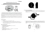
Remove the cable.
Loosen the screws (four M4 screws),
remove the transmitter-receiver unit
cover, and remove the cables
connected to the transmitter-receiver
unit (ten cables). Slide the cover of
the transmitter-receiver unit to remove
it.
4
Remove the transmitter-receiver.
Loosen the bolts (five M5 bolts) and
remove the transmitter-receiver unit.
Slide the transmitter-receiver unit
upward to remove it.
Slide the cover.
Loosen the four
screws.
Slide the unit.
Loosen the five
bolts.
Summary of Contents for JMR-7210-6X
Page 2: ......
Page 62: ...Section 19 Adjusting and Setting up Equipment for Services 19 50...
Page 230: ...Section 22 Failures and After Sale Services 22 52...
Page 286: ......
Page 304: ......
Page 426: ...Appendix D Menu List and Materials D 34 D 1 16 Code Input Password ECDIS RADAR CONNING...
Page 585: ......


