Section 11 Setting up Screen View
11-12
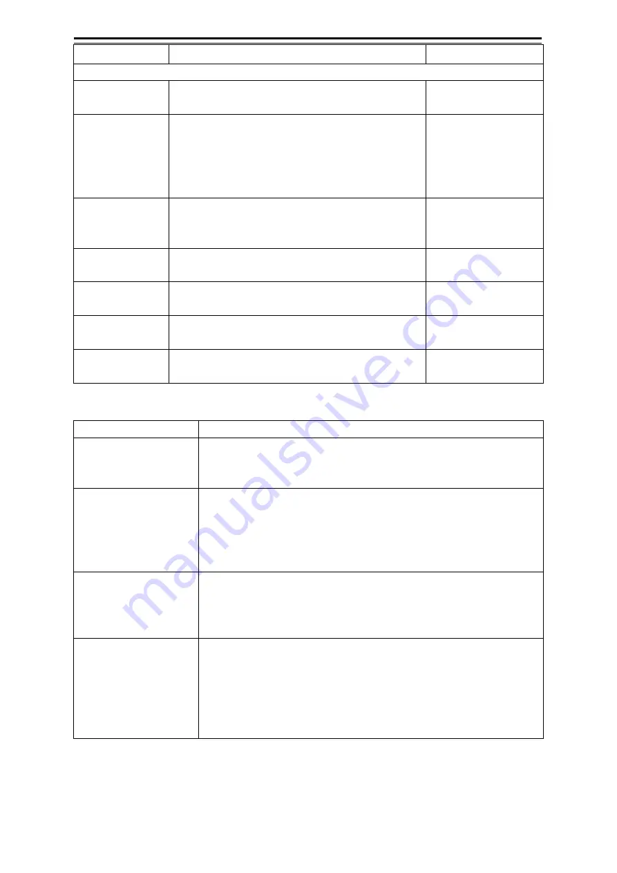
Setting Item
Description of Setting
Setting Value
Page4
VAD(Value Added
Data)
Display/hide the value added data object.
Shown: Selected
Hidden: Clear
Chart Boundaries Display/hide the chart boundaries.
To display the chart boundaries, select the check box
and select the detail setting from the combo box.
Check box
Shown: Selected
Hidden: Clear
Combo box
AUTO/Full
Wrecks Depth
Label
Display/hide the wreck label.
Wreck label: Digit that is displayed next to the wreck
object.
Shown: Selected
Hidden: Clear
Diffusers Depth
Label
Display/hide the diffuser label.
Shown: Selected
Hidden: Clear
Obstructions
Depth Label
Display/hide the obstruction label.
Shown: Selected
Hidden: Clear
Rocks Depth
Label
Display/hide the rock label.
Shown: Selected
Hidden: Clear
Graticule
Display/hide the latitude/longitude lines.
Shown: Selected
Hidden: Clear
Water depth shadow mode
Mode
Description
Normal
Display the depth shadow range of the UKHO (United Kingdom
Hydrographic Office) accurately. The depth shadow is expressed in three
colours (Dark Blue, Light Blue, and White) only.
Safe
Although the expression is the same as that of the [Normal] mode, two
colours can be used instead of three colours. A safe depth threshold
value can be set and the safe depth (depth greater than the threshold
value) is expressed in Blue. The colour of safe depth is Green and other
depths are expressed in Grey.
Dynamic
Express a depth shadow in 32 types of Blue. In [Dynamic] mode, a
minimum depth and a maximum depth can be set. Shallows are
expressed in a darker shading of Blue. White indicates the depth greater
than the maximum depth.
Dynamic Inverted
Although the expression is the same as that of the [Dynamic] mode, the
depth shadow is expressed by the inverted algorithm. In the same way as
the dynamic mode, a minimum depth and a maximum depth can be
specified. Shallows are expressed in a lighter shading of Blue and
offshore is expressed in darker blue. White indicates the depth shallower
than the minimum depth.
Summary of Contents for JMR-5410-4X
Page 2: ......
Page 25: ...xxiii NKE 2255 7 9 6HS Scanner Unit Warning Label ...
Page 27: ...xxv NKE 2103 4 4HS Scanner Unit NKE 2103 6 6HS Scanner Unit NKE 2255 7 9 6HS Scanner Unit ...
Page 54: ...Contents 20 ...
Page 68: ...Section 1 Overview 1 14 Outline Drawing of Radar Antenna NKE 2632 A ...
Page 70: ...Section 1 Overview 1 16 Outline Drawing of Radar Antenna NKE 2043 NKE 2043 ...
Page 72: ...Section 1 Overview 1 18 Outline Drawing of Radar Antenna NKE 2103 4 4HS ...
Page 74: ...Section 1 Overview 1 20 Outline Drawing of Radar Antenna NKE 2255 7 ...
Page 76: ...Section 1 Overview 1 22 Outline Drawing of Radar Antenna NKE 2255 6HS ...
Page 78: ...Section 1 Overview 1 24 Outline drawing of 19inch Display NWZ 214 NWZ 214 ...
Page 80: ...Section 1 Overview 1 26 Outline Drawing of Process Unit NDC 1678 NDC 1678 ...
Page 82: ...Section 1 Overview 1 28 Outline Drawing of Trackball Operation Unit NCE 5605 Option ...
Page 84: ...Section 1 Overview 1 30 Outline Drawing of Junction Box NQE 1143 ...
Page 86: ...Section 1 Overview 1 32 Outline Drawing of 19inch Desktop Frame CWB 1659 ...
Page 88: ...Section 1 Overview 1 34 Outline Drawing of Interswitch Unit NQE 3141 8A Option ...
Page 126: ......
Page 214: ...Section 4 Range and Bearing Measurement Methods 4 32 ...
Page 244: ...Section 5 Basic Operation of the Radar 5 30 ...
Page 324: ...Section 8 Monitoring a Dragging Anchor 8 8 ...
Page 374: ...Section 11 Setting up Screen View 11 20 ...
Page 520: ...Section 15 Maintenance Inspection 15 70 ...
Page 546: ...Section 16 Failures and After Sale Services 16 26 ...
Page 590: ...Appendix A Radar Antenna Display Unit Block Diagrams A 8 A 1 8 NKE 2255 7 9 6HS ...
Page 592: ...Appendix A Radar Antenna Display Unit Block Diagrams A 10 A 1 10 NKE 2063A ...
Page 596: ...Appendix A Radar Antenna Display Unit Block Diagrams A 14 A 2 3 NCE 5794 operation unit ...
Page 622: ...Appendix D Menu List and Materials D 8 Tools VHF Call VHF1 Call VHF2 Call VHF3 Call ...
Page 687: ......


