


JOHNSON CONTROLS
44
FORM 201.23-NM2
ISSUE DATE: 3/9/2015
SECTION 4 - INSTALLATION
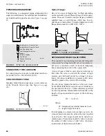
Where accumulation of snow is likely, additional
height must be provided under the unit to ensure nor-
mal airflow to the unit
Clearance dimensions provided elsewhere
are necessary to maintain good airflow
and ensure correct unit operation. It is
also necessary to consider access require-
ments for safe operation and maintenance
of the unit and power and control panels.
Local health and safety regulations,
or practical considerations for service
replacement of large components, may
require larger clearances than those given
in the SECTION 6 - TECHNICAL DATA
(Page
61).
VIBRATION ISOLATORS
Optional sets of vibration isolators can be supplied
loose with each unit.
Using the Isolator tables shipped with the unit in the
information pack, refer to the
,
Spring Isolators Cross-Reference on page 162
for
units shipped on or after June 15, 2008 and
Deflection Spring Isolators Installation Instructions
for units shipped before June 15, 2008).
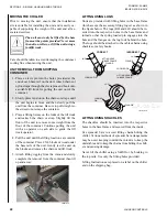
Identify each mount and its correct location on the unit.
Installation
Place each mount in its correct position and lower the
unit carefully onto the mounts ensuring the mount en-
gages in the mounting holes in the unit base frame.
On adjustable mounts, transfer the unit weight evenly
to the springs by turning the mount adjusting nuts (lo-
cated just below the top plate of the mount) counter-
clockwise to raise and clockwise to lower. This should
be done two turns at a time until the top plates of all
mounts are between 1/4" and 1/2" (6 and 12 mm) clear
of top of their housing and the unit base is level.
A more detailed installation instruction
is provided on Pages 164 through 169 for
units shipped on or after June 15, 2008
and Pages 170 through 174 for units
shipped before June 15, 2008.
SHIPPING BRACES
The chiller’s modular design does not require shipping
braces.
CHILLED LIQUID PIPING
General Requirements
The following piping recommendations are intended to
ensure satisfactory operation of the unit(s). Failure to
follow these recommendations could cause damage to
the unit, or loss of performance, and may invalidate the
warranty.
The maximum flow rate and pressure drop
for the cooler must not be exceeded at any
time. Refer to SECTION 6 - TECHNICAL
DATA (Page
61)
The liquid must enter the cooler at the
inlet connection. The inlet connection
for the cooler is at the control panel end
of the cooler.
A flow switch must be installed in the customer pip-
ing at the outlet of the cooler and wired back to the
control panel using shielded cable.
There should be a straight run of piping of at least 5
pipe diameters on either side. The flow switch should
be wired to Terminals 2 and 13 on the 1TB terminal
block (See
Figure 32 on page 183 and Figure 33 on
). A flow switch is required to prevent dam-
age to the cooler caused by the unit operating without
adequate liquid flow.
The flow switch used must have gold plated contacts
for low voltage/current operation. Paddle type flow
switches suitable for 150 PSIG (10 bar) working pres-
sure and having a 1" N.P.T. connection can be obtained
from YORK as an accessory for the unit. Alternatively,
a differential pressure switch fitted across an orifice
plate may be used, preferably of the high/low limit
type.
The chilled liquid pump(s) installed in the piping
system(s) should discharge directly into the unit cooler
section of the system. The pump(s) may be controlled
by the chiller controls or external to the unit. For de-
tails, refer to “Electrical Elementary and Connection
Diagrams.”
Summary of Contents for YCIV0157
Page 38: ...JOHNSON CONTROLS 38 FORM 201 23 NM2 ISSUE DATE 3 9 2015 THIS PAGE INTENTIONALLY LEFT BLANK ...
Page 42: ...JOHNSON CONTROLS 42 FORM 201 23 NM2 ISSUE DATE 3 9 2015 THIS PAGE INTENTIONALLY LEFT BLANK ...
Page 50: ...JOHNSON CONTROLS 50 FORM 201 23 NM2 ISSUE DATE 3 9 2015 THIS PAGE INTENTIONALLY LEFT BLANK ...
Page 333: ...JOHNSON CONTROLS 333 FORM 201 23 NM2 ISSUE DATE 3 9 2015 NOTES ...


