
JOHNSON CONTROLS
221
SECTION 7 - OPERATION
FORM 201.23-NM2
ISSUE DATE: 3/9/2015
7
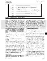
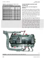
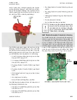
The Feed Valve is a stepper motor valve that controls
the liquid flow from the condenser to assure the liquid
level in the flash tank is maintained at a proper level.
The Level Sensor is a rod inserted into the reservoir
connected to the side of the flash tank. The sensing rod
has an active range of about 12”.
The control algorithm looks at feedback from the Level
Sensor and compares it to the fixed level setpoint in
the control algorithm. This control strategy attempts to
keep the level in the flash tank to approx 35% of the
usable portion of the sensing rod. In reality, this is ap-
proximately a 50% level in the flash tank. As the level
in the flash tank fluctuates, the control algorithm var-
ies the voltage to the Controller, which in turn sends a
2 phase stepped drive signal to open or close the Feed
Valve as needed.
As the flash tank level varies farther from the setpoint,
the gain of the control algorithm increases for faster
response. In some cases, the Feed Valve will fully open
or fully close if the levels become too low or too high.
When properly charged, the condenser subcooling will
be approx. 5-7°F at design conditions as the Feed Valve
controls refrigerant flow into the flash tank.
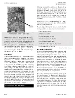
The Drain Valve is also a stepper motor valve. Like the
Feed Valve, the controller receives a 0 to 10.28VDC
signal from the Chiller Control Board. The control-
ler then converts the signal to a valve position and a
2 phase signal drives the Drain valve open or closed.
The Drain Valve, Controller, and Chiller Control Board
Algorithm combination functions as an Electronic Ex-
pansion Valve (EEV). The controller receives an ana-
log 0 to 10.28VDC signal sent from the Chiller Control
Board, which is based on system suction pressure and
suction temperature. These operating parameters are
used to compute and control suction superheat accord-
ing to the Setpoint programmed into the panel under
the PROGRAM key. After computing the superheat,
the signal to the controller is adjusted and the control-
ler subsequently positions the Drain Valve to control
the superheat. The gain of the control algorithm is ad-
justed to aid in correcting for superheat error.
The Chiller Control Board Algorithm assures the level
in the flash tank does not become too high. The level
setpoint for control is 35%. Levels normally run 30 to
40% with the economizer solenoid energized (open).
With the solenoid closed, levels may vary significantly
from the 30 to 40% level. If the level exceeds 85% of
the full level, the system will shut down on a fault.
The Feed and Drain Valves in a system open and be-
gin to control as soon as a compressor starts. When the
compressor shuts down, the valves are driven to their
closed position.
MOP Setpoint Control for Hot Water Starts
Maximum Operating Pressure control overrides super-
heat control of the Drain Valve when the MOP Setpoint
is exceeded on hot water starts. The fixed setpoint is
68°F Saturated Suction Temp (SST). When this value
is exceeded, the Drain Valve switches superheat con-
trol to suction pressure control equal to 68°F SST.
Moderate To High Ambient MOP Setpoint
Control.
In moderate to high ambients, the suction line may be
warmed by the ambient, contributing to inaccurate suc-
tion superheat measurement at start-up. To avoid this
situation, the MOP control utilizes suction pressure con-
trol at start-up, which overrides superheat control. For
the first minute of run time, the MOP Setpoint is set to:
RCHLT - Superheat Setpoint – 1.0°F
Run Time in Seconds
After the first minute of operation, the MOP Setpoint is
ramped from the current calculated value to 68°F over
the next minute. At this point, normal superheat control
based on the programmed setpoint resumes.
Low Ambient MOP Setpoint Control
In low ambient start-ups, suction pressure is erratic and
pressure differentials across the compressor may be low,
resulting in low oil differential faults. The Low Ambi-
ent MOP setpoint control assures adequate differential
is developed between discharge and suction to push oil
through the oil cooling system and the compressor.
For the first 5 minutes of system run time, the MOP
Setpoint is set to the saturated suction temperature
equal to 15PSIG below discharge pressure, which
overrides superheat control. The control algorithm will
not allow suction pressure control below the cutout.
The low limit of the suction pressure is the low suction
pressure cutout. After 5 minutes of system run time,
the MOP Setpoint is set at 68°F and superheat control
based on the programmed setpoint resumes.
Actual MOP Setpoint
The actual MOP Setpoint used by the controller is
the minimum of three calculations; the fixed MOP
Setpoint, the moderate to high ambient setpoint, and
the low ambient setpoint.
Summary of Contents for YCIV0157
Page 38: ...JOHNSON CONTROLS 38 FORM 201 23 NM2 ISSUE DATE 3 9 2015 THIS PAGE INTENTIONALLY LEFT BLANK ...
Page 42: ...JOHNSON CONTROLS 42 FORM 201 23 NM2 ISSUE DATE 3 9 2015 THIS PAGE INTENTIONALLY LEFT BLANK ...
Page 50: ...JOHNSON CONTROLS 50 FORM 201 23 NM2 ISSUE DATE 3 9 2015 THIS PAGE INTENTIONALLY LEFT BLANK ...
Page 333: ...JOHNSON CONTROLS 333 FORM 201 23 NM2 ISSUE DATE 3 9 2015 NOTES ...


