


JOHNSON CONTROLS
298
FORM 201.23-NM2
ISSUE DATE: 3/9/2015
SECTION 8 - MICROPANEL
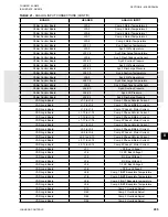
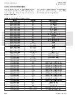
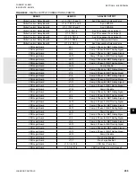
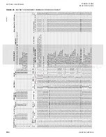
DIGITAL OUTPUT CONNECTIONS
lists the digital outputs and the
plug/terminals of the circuit board they originate from.
Not all of the outputs will be used on every unit. Sig-
nal levels may be 12VDC, 120VAC, or a dry contact
(no voltage) closure). 120VAC signals typically may
show only one connection point; the other will be neu-
tral (Wire 2). Outputs which reference multiple boards,
such as “Chiller Control Board / Relay Board 1” indi-
cate the signal originates on the Chiller Control Board
as a 0 to 12VDC digital signal (example: J9-1) that is
then fed to the Relay board and output as a dry contact
closure between TB1-20 and 19. In this case, outputs
from both boards are called out in the table.
The 0 to 120VAC single digital outputs from the Relay
Output Boards are referenced to neutral (Wire 2). For
example, the fan output on TB1-6 is a single 120VAC
output. The 0 to 12VDC outputs from the Chiller Con-
trol Board are referenced to common (return, ground)
in the system. J12-3 can also be used as common, as
well as chassis ground, or the common terminal point
on the Chiller Control Board. See the wiring diagrams.
Refer to the wiring diagrams whenever there is a re-
quirement for tracing out these signals.
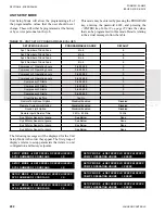
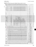
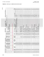
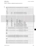
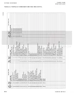
TABLE 24 -
DIGITAL OUTPUT CONNECTIONS
BOARD
HEADER
ANALOG OUTPUT
Chiller Control / Relay Board 1
J9-1 / TB1-20 and 19
Evaporator Heater
Chiller Control / Relay Board 1
J9-2 / TB1-18 and 17
Sys 1/3 VSD Run
Chiller Control / Relay Board 1
J9-3 / TB1-16 and 15
Sys 1/3 Alarm
Chiller Control / Relay Board 1
J9-4 / TB1-14 and 13
Evaporator Heater 2
Chiller Control / Relay Board 1
J9-5 / TB1-12 and 11
Sys 1 SPARE
Chiller Control / Relay Board 1
J9-6 / TB1-10 and 9
SPARE
Chiller Control / Relay Board 1
J9-7/ TB1-8 and 7
SPARE
Chiller Control / Relay Board 1
J9-8 / TB1-6
Sys 1 Condenser Fans Output 1
Chiller Control / Relay Board 1
J9-9 / TB1-5
Sys 1 Condenser Fans Output 2
Chiller Control / Relay Board 1
J9-10 / TB1-4
Sys 1 Condenser Fans Output 3
Chiller Control / Relay Board 1
J9-11 / TB1-3
Sys 1 Compressor Heater
Chiller Control / Relay Board 1
J9-12 / TB1-2
Sys 1 Economizer Solenoid Valve
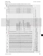
Chiller Control / Relay Board 2
J10-1 / TB1- 20 and 19
Evaporator Pump Start
Chiller Control / Relay Board 2
J10-2 / TB1-18 and 17
Sys 2/4 VSD Run
Chiller Control / Relay Board 2
J10-3 / TB1-18 and 15
Sys 2/4 Alarm
Chiller Control / Relay Board 2
J10-4 / TB1-16 and 14
Chiller Run
Chiller Control / Relay Board 2
J10-5 / TB1-12 and 11
Sys 2 SPARE
Chiller Control / Relay Board 2
J10-6 / TB1-10 and 9
SPARE
Chiller Control / Relay Board 2
J10-7 / TB1-8 and 7
SPARE
Chiller Control / Relay Board 2
J10-8 / TB1-6
Sys 2 Condenser Fans Output 1
Chiller Control / Relay Board 2
J10-9 / TB1-5
Sys 2 Condenser Fans Output 2
Chiller Control / Relay Board 2
J10-10 / TB1-4
Sys 2 Condenser Fans Output 3
Chiller Control / Relay Board 2
J10-11 / TB1-3
Sys 2 Compressor Heater
Chiller Control / Relay Board 3
J10-12 / TB1-2
Sys 2 Economizer Solenoid Valve
Chiller Control / Relay Board 3
J11-1 / TB1-20 and 19
Sys 4 Condenser Fan Output 1
Chiller Control / Relay Board 3
J11-2 / TB1-18 and 17
Sys 4 Condenser Fan Output 2
Chiller Control / Relay Board 3
J11-3 / TB1-16 and 15
Sys 4 Condenser Fan Output 3
Chiller Control / Relay Board 3
J11-4 / TB1-14 and 13
Sys 4 Compressor Heater
Summary of Contents for YCIV0157
Page 38: ...JOHNSON CONTROLS 38 FORM 201 23 NM2 ISSUE DATE 3 9 2015 THIS PAGE INTENTIONALLY LEFT BLANK ...
Page 42: ...JOHNSON CONTROLS 42 FORM 201 23 NM2 ISSUE DATE 3 9 2015 THIS PAGE INTENTIONALLY LEFT BLANK ...
Page 50: ...JOHNSON CONTROLS 50 FORM 201 23 NM2 ISSUE DATE 3 9 2015 THIS PAGE INTENTIONALLY LEFT BLANK ...
Page 333: ...JOHNSON CONTROLS 333 FORM 201 23 NM2 ISSUE DATE 3 9 2015 NOTES ...


