

JOHNSON CONTROLS
222
FORM 201.23-NM2
ISSUE DATE: 3/9/2015
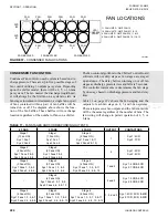
SECTION 7 - OPERATION
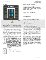
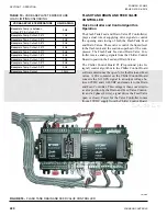
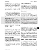
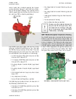
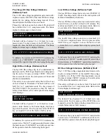
Valve Controller LED’s
The Drain and Feed Valve stepper motor controller is
equipped with a pair of LED’s on the left side of the
module and 10 LED’s in the center of the module (
). These LED’s may be useful dur-
ing troubleshooting.
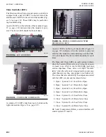
A pair of LED’s on the left side of the module (
) indicate when the module is pow-
ered. The Power LED should be lit at all times.
FIGURE 54 -
LED LOCATIONS
LD10629
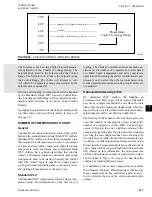
FIGURE 55 -
POWER AND COMMS LED'S
LD10630
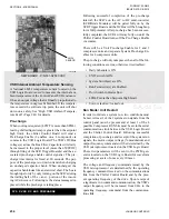
A column of 10 LED’s runs from top to bottom on the
FIGURE 56 -
POWER, COMMS AND SYSTEM
OPEN/CLOSE LED'S
LD10631
A pair of LED’s on the top of the module (
) indicates when the module is powered
and when the module is communicating with the Chill-
er Control Board. The Power LED should be lit at all
times.
The Open and Close LED’s on each system indicate
when the Feed and Drain valves are being driven open
or closed in an effort to control flash tank level and
suction superheat. These valves will light “momen-
tarily” when the valves are being pulsed. In most cases
other than start-up, they may appear to not light at all.
The valves that are controlled by the outputs associated
with the LED’s are decoded as shown below:
1. Open = System #1 or 3 Feed Valve Open
2. Open = System #1 or 3 Drain Valve Open
3. Open = System #2 or 4 Feed Valve Open
4. Open = System #2 or 4 Drain Valve Open
5. Close = System #1 or 3 Feed Valve Close
6. Close = System #1 or 3 Drain Valve Close
7. Close = System #2 or 4 Feed Valve Close
8. Close = System #2 or 4 Drain Valve Close
On 3 and 4 compressor chillers, a second module will
control systems #3 and #4.
Summary of Contents for YCIV0157
Page 38: ...JOHNSON CONTROLS 38 FORM 201 23 NM2 ISSUE DATE 3 9 2015 THIS PAGE INTENTIONALLY LEFT BLANK ...
Page 42: ...JOHNSON CONTROLS 42 FORM 201 23 NM2 ISSUE DATE 3 9 2015 THIS PAGE INTENTIONALLY LEFT BLANK ...
Page 50: ...JOHNSON CONTROLS 50 FORM 201 23 NM2 ISSUE DATE 3 9 2015 THIS PAGE INTENTIONALLY LEFT BLANK ...
Page 333: ...JOHNSON CONTROLS 333 FORM 201 23 NM2 ISSUE DATE 3 9 2015 NOTES ...


