


JOHNSON CONTROLS
201
SECTION 6 - TECHNICAL DATA
FORM 201.23-NM2
ISSUE DATE: 3/9/2015
6
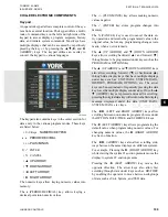
commands to the Relay Output Board(s), Drain/Feed
Valve Controller, and VSD Logic Board to activate
and de-activate contactors, solenoids, control valves,
set compressor speeds, etc., for chilled liquid and
safety control. Keypad commands are acted upon by
the Chiller Control Board microprocessor to change
setpoints, cutouts, scheduling, operating requirements,
and to provide displays.
The Chiller Control Board contains a Real Time Clock
integrated circuit chip with an internal battery backup
of 8K x 8 bit RAM. The purpose of the battery backed
RAM is to assure any programmed values (setpoints,
clock, cutouts, history data etc.) are not lost during
a power failure, regardless of the time involved in a
power outage or shutdown period.
The Chiller Control (Microprocessor) Board contains
an onboard power supply, which provides 5VDC regu-
lated to sensors, transducers, display, and other circuit
boards. The supply also pr12VDC to the Relay
Output Boards and the +34VDC to the level sensors.
The Chiller Control Board is capable of directly
receiving analog inputs from temperature sensors and
transducers. An analog to digital converter (A/D) with
an onboard 4 channel multiplexer (MUX) allows up to
48 analog inputs to be read. The A/D Converter con-
verts the analog signals to digital signals, which can
be read by the onboard microprocessor. On a 2 system
chiller, approximately half of these inputs are utilized.
Three integrated circuits on the microprocessor can be
configured for digital inputs or outputs (Digital I/O).
As inputs, they can read digital (2 level, on/off) inputs
like keypad keys, unit switch, high pressure cut-out,
flow switch, etc. As outputs they are used for controls
like turning on fans, controlling compressor heaters,
controlling chiller valves, or other devices requiring
ON/OFF control. Up to 72 Digital I/O will be utilized
to control the chiller.
The Chiller Control (Microprocessor) Board contains
a dual UART (Universal Asynchronous Receiver
Transmitter) for RS-485 and RS-232 communications.
UART1 is configured for RCC and ISN communica-
tions on the external chiller RS-485 port. Data is sent
and received at 4800 baud with 1 start bit, 8 data bits,
odd parity, and 1 stop bit. The port is shared with the
RS-232 interface and at start-up will be initialized to
RS-485 communications. UART2 is configured for
VSD communications over an internal chiller RS-485
port located within the Control/Power cabinet. UART2
has a higher priority interrupt than UART1. The data
is sent and received at a rate of 9600 baud and serves
only as the communications between the Chiller Con-
trol Board and the VSD Logic Board. Both of these
boards are located within the control/power panel.
On power-up, the Chiller Control Board will attempt to
initialize communications with the VSD Logic Board.
The Chiller Control Board will request the number of
compressors select and VSD software version. If for
some reason the information is not provided, the re-
quest will be made over and over again until it is re-
ceived. Once the data has been received, the Chiller
Control Board will not ask for it again. If the communi-
cations is not established, a VSD Loss Of Comms fault
message will appear on the STATUS display.
Two 8 channel, 8 bit Digital to Analog Converters (D/A
Converter) on the Chiller Control Board supply the
Feed and Drain Valve Controller signals to allow the
controller to position the Flash Tank Feed and Drain
Valves. The Feed Valve controls the refrigerant level
in the flash tank while the Drain Valves controls super-
heat. The control voltage to the Feed and Drain Valve
Controller has a range of 0 to 10.28VDC.
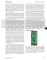
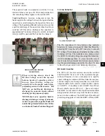
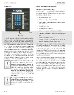
Relay Output Boards
LD10607
Two or three Relay Output Boards are required to
operate the chiller. These boards convert 0 to 12VDC
logic levels outputs from the Chiller Control Board to
115VAC levels used by contactors, relays, solenoid
valves, etc., to control system and chiller operation.
The common side of all relays on the Relay Output
Board is connected to +12VDC.
Summary of Contents for YCIV0157
Page 38: ...JOHNSON CONTROLS 38 FORM 201 23 NM2 ISSUE DATE 3 9 2015 THIS PAGE INTENTIONALLY LEFT BLANK ...
Page 42: ...JOHNSON CONTROLS 42 FORM 201 23 NM2 ISSUE DATE 3 9 2015 THIS PAGE INTENTIONALLY LEFT BLANK ...
Page 50: ...JOHNSON CONTROLS 50 FORM 201 23 NM2 ISSUE DATE 3 9 2015 THIS PAGE INTENTIONALLY LEFT BLANK ...
Page 333: ...JOHNSON CONTROLS 333 FORM 201 23 NM2 ISSUE DATE 3 9 2015 NOTES ...


