


Reference Diagrams & Schematics
D-94
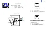
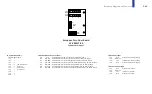
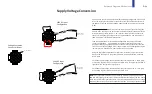
Supply Voltage Conversion
Pin 1 “rib” indicator
1
2
3
4
5
6
7
8
9
1
2
3
4
5
6
7
8
9
220V AC Input
Configuration
220V AC supplied
across these lines
1
2
3
4
5
6
7
8
9
120V AC Input
Configuration
120V AC supplied
across these lines
Voltage Conversion
Connector Pin-out
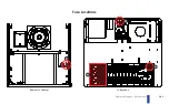
If you need to convert your game to a different supply voltage than it was wired
for at the factory, locate the 9-pin connector at the input of the transformer, in
the bottom of the lower cabinet (shown opposite and in the green box on page
D-92).
Power the game down
and disconnect the 9-pin connector (it has locking tabs
on each side). Looking at the back of the jumpered connector (the end with the
wires protruding), locate the pin 1 “rib” indicator and orient the connector so
that it is in the upper right hand corner, as shown opposite. The red numbers
show pin numbers for the entire connector.
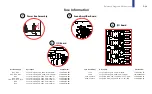
Look at the illustration for the desired configuration and compare it to the
current configuration. Using a 0.084” pin extractor, remove all pins that re-
quire repositioning by pushing them out of the back of the connector, from the
front. You can reuse existing wires as long as they were not damaged during the
removal process. Fashion new, short jumper wires, as needed.
Using the appropriate illustration for reference, insert the jumper pins all the
way into the connector, in the proper positions, from the back side, until they
lock in place.
For a 120V supply voltage, connect the AC inputs across pins 1 & 7. Next, jump-
er pins 2 & 3 together with a short piece of black wire. Lastly, jumper pins 8 & 9
together with a short piece of orange wire.
For a 220V supply voltage, connect the AC inputs across pins 1 & 4. Then jump-
er pins 3 & 9 together with a short piece of black wire.
Note:
Your POTC game makes use of a switching, modular power supply for the
RGB LED & GI lighting systems (5V), the sound amplifier board (12V), the CPU board
(5V & 12V) and/or other game functions. This switching power supply has a voltage
selection slide switch on its exterior panel that must be in the proper position (120V
or 220V) before applying power to the game.
Summary of Contents for Pirates of the Caribbean
Page 2: ......
Page 13: ...Game Assembly Setup A 1 Game Assembly Setup Section A...
Page 37: ...The POTC Menu System B 1 The POTC Menu System Section B...
Page 93: ...Game Parts Information C 1 Game Parts Information Section C...
Page 98: ...Game Parts Information C 6 1 2 3 4 5 6 7 8 9 14 12 16 11 10 13 15...
Page 112: ...Game Parts Information C 20 1 2 5 9 3 13 6 10 4 15 16 11 8 7 12 18 17 14 12 18 17 14...
Page 114: ...Game Parts Information C 22 2 4 12 3 16 17 10 11 5 7 6 18 8 14 9 13 1 15 8...
Page 146: ...Game Parts Information C 54 7 14 1 4 9 11 3 2 5 8 8 10 10 12 13 15 16 16 17 6...
Page 166: ...Game Parts Information C 74 15 1 25 2 3 4 5 6 9 10 11 12 13 14 19 17 18 20 21 26 27 28...
Page 168: ...Game Parts Information C 76 1 2 3 4 5 6 9 10 11 12 13 14 15 25 17 18 20 19 26 21 27 28...
Page 170: ...Game Parts Information C 78 49 51 50 55 56 41 42 43 44 45 46 46 46 47 48 76 77 46...
Page 172: ...Game Parts Information C 80 49 51 50 55 56 41 42 43 44 45 46 46 46 47 48 76 77...
Page 200: ...Game Parts Information C 108 79 65 69 70 71 72 73 74 75 76 77 78 81 80 82 83 84 85 86 87 88...
Page 202: ...Game Parts Information C 110 9 10 12 13 14 15 66 67 68 9 10 12 15 13 14 66 67 68...
Page 208: ...Game Parts Information C 116 32 79 65 69 70 71 72 75 74 73 76 77 78 80 81 82 83 84 85 86 87 88...
Page 212: ...Game Parts Information C 120 23 16 4 6 15 12 10 9 5 2 3 17 13 18 7 22 8 21 20 19 27...
Page 214: ...Game Parts Information C 122 1 14 25 24 11 26 26 26 26 34 32 32 32 30 31 31...
Page 216: ...Game Parts Information C 124 8 3 4 5 1 2 6 7...
Page 220: ...Game Parts Information C 128 0 1 14 2 3 5 4 11 7 6 9 10 12 15...
Page 222: ...Game Parts Information C 130 13 4 5 5 4 4 3 1 2 2 1 7 6 6 6 6 6 6 6 6 6 6 6 6 8 8 8 13 13...
Page 230: ...Game Parts Information C 138 1 2 3 4 5 10 9 8...
Page 232: ...Game Parts Information C 140 1 1 1 2 2 3 3 4 5 8 7 7 7 7 7 7...
Page 234: ...Game Parts Information C 142 1 1 1 1 1 1 1 1 1 1...
Page 248: ...Game Parts Information C 156...
Page 249: ...Reference Diagrams Schematics D 1 Reference Diagrams Schematics Section D...
Page 302: ...Reference Diagrams Schematics D 54...
Page 308: ...Reference Diagrams Schematics D 60...
Page 337: ...Reference Diagrams Schematics D 89 1 Fuse Locations Bottom of Cabinet 4 2 3 In Backbox...
Page 343: ...Game Service Troubleshooting E 1 Game Service Troubleshooting Section E...
Page 353: ...Appendices...
Page 358: ......