91
12
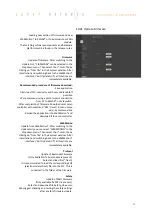
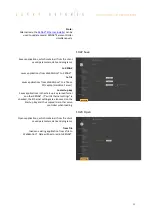
Gantry Synchronized Mode
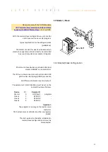
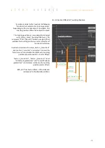
In the gantry mode there are two linear motor axes
mounted with the same driving direction. Those two
axes have to move synchronously. In this example
these are the y-axes marked with the arrows.
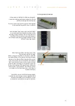
When switching on the system, these two Y-axes
have to be aligned in order to move without
mechanical tension.
The alignment is automatically completed with the
function “REFERENCE”. For “REFERENCE” function for
gantry systems you will need the following
information:
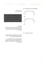
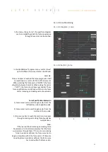
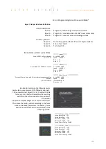
The arrangement of the two linear motor axes
Is driving direction from the mechanical absolute zero
point the same for both axes or in opposite direction
In which direction should the reference be completed
(parameter DRHR)
12.1
Activate Gantry Mode
The axis with which will be communicated by ASCII
commands is the master. The slave has to be
connected to the master via A-A cable.
The slave has to be assigned a CARD IDENTIFIER
between 1 and 3. This can be done by WebMotion®
under “
setup
/ basic / CARD IDENTIFIER”
or with ASCII
command
CI x (where x = 1-3).
The card identifier (CI) can also be assigned with a
start-up key and an address from 1 to 3. When
turning on the logic supply the next time, this CI
number of the start-up key is set.
The master has to be assigned to the number 0 or a
different Card identifier (CI) than its slave.
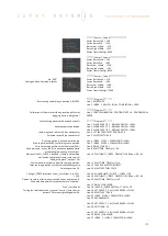
The gantry mode is activated with these settings.
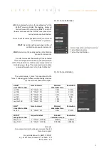
XENAX®
Parameter
Description
SLAVE
CI
Card Identifier
MASTER
DRHR
Direction of reference
drive and arrangement
LINAX® / ELAX® linear
motor axes.
MASTER
GSID
Gantry Slave ID
corresponds to CI Slave
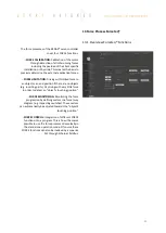
Settings WebMotion®
(settings only necessary on the XENAX® Master)
Corresponds to DRHR
Corresponds to GSID
Corresponds to CI
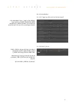
Master-Slave
USB A-A cable


