


Subject to change without notice!
Installation and Operating Instructions ECOVARIO® 616, 616 D
53
6.8.4
X22: Designs with EtherCAT® interface
As an option, ECOVARIO® can be equipped with an EtherCAT® interface which can be used for setpoint
setting and parameterization. Th e interface supports the protocol of the EtherCAT® Technology Group and
allows for Fast Ethernet according to IEEE-802.3u (100Base-TX), fullduplex, 100Mbps. Physically, the in-
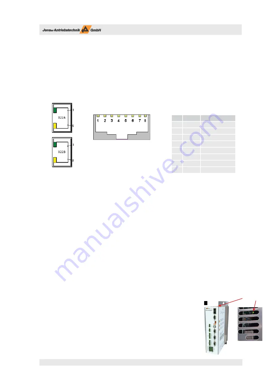
terface is designed as two standardized RJ45-sockets at the front side of the ECOVARIO®. Pin assignment is
the same as for the standard Ethernet interface (c.f. Chap. 6.8.3).
OUT
IN
Th e interface X22B is the EtherCAT® „IN“ port and is used for the
connection to the PC or a server (end of a star-shaped connection).
Th e interface X22A is the EtherCAT® „OUT“ port and is intended for the connection to further servo am-
plifi ers via a line-shaped connection (uplink, cf. examples below).
Cabling is done via twisted-pair-cables UTP, Cat.5e. Tree and line topologies are supported. Star topologies
are possible as well. Th e cable length between two devices is limited to 100 m.
For process control and visualization of EtherCAT® devices the operation with the PC soft ware „TwinCAT“
(manufacturer: Beckhoff GmbH) is proposed. For confi guration instructions and an application example
please refer to Application Note 26.
he objects which are required for the confi guration of the EtherCAT® communication are described in the
manual „Object Dictionary ECOVARIO, ECOSTEP, ECOMPACT, chapter 5.2.29.
Th e interfaces X22A and X22B are each equipped with the following display elements:
green LED displays „Link / Activity“
orange LED displays „Transmission in fullduplex mode“.
Th e green „RUN“ LED is located in the housing of the ECOVARIO and can be seen
through the air slots on the upper side of the housing. Th e LED has the following functions:
LED off :
EtherCAT® State Init
LED fl ashes (5 Hz):
EtherCAT® State Pre-Operational
LED fl ashes (200ms on/1s off ): EtherCAT® State Safe Operational
LED on:
EtherCAT® State Operational
Pin
Signal
Description
1
RX+
Receive
2
RX-
Receive signal -
3
TX+
Transmit
4
-
n.c.
5
-
n.c.
6
TX-
Transmit signal -
7
-
n.c.
8
-
n.c.
Table 6.25: Pin assignment connector
X22A,B on design with EtherCAT® interface
„RUN“ LED