microprocessors. A logic block in each microprocessor
receives identical sensor signals. These signals are
processed and compared simultaneously. The CAB
contains a self check program that illuminates the
ABS warning light when a system fault is detected.
Faults are stored in a diagnostic program memory
and are accessible with the DRB scan tool. ABS
faults remain in memory until cleared, or until after
the vehicle is started approximately 50 times. Stored
faults are not erased if the battery is disconnected.
HYDRAULIC CONTROL UNIT
DESCRIPTION
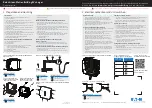
The HCU consists of a valve body, pump motor,
and wire harness (Fig. 1).
OPERATION
Accumulators in the valve body store extra fluid
released to the system for ABS mode operation. The
pump provides the fluid volume needed and is oper-
ated by a DC type motor. The motor is controlled by
the CAB.
The
valves
modulate
brake
pressure
during
antilock braking and are controlled by the CAB.
The HCU provides three channel pressure control
to the front and rear brakes. One channel controls
the rear wheel brakes in tandem. The two remaining
channels control the front wheel brakes individually.
During antilock braking, the solenoid valves are
opened and closed as needed. The valves are not
static. They are cycled rapidly and continuously to
modulate pressure and control wheel slip and decel-
eration.
During normal braking, the HCU solenoid valves
and pump are not activated. The master cylinder and
power booster operate the same as a vehicle without
an ABS brake system.
During antilock braking, solenoid valve pressure
modulation occurs in three stages, pressure increase,
pressure hold, and pressure decrease. The valves are
all contained in the valve body portion of the HCU.
PRESSURE DECREASE
The outlet valve is opened and the inlet valve is
closed during the pressure decrease cycle.
A pressure decrease cycle is initiated when speed
sensor signals indicate high wheel slip at one or
more wheels. At this point, the CAB closes the inlet
then opens the outlet valve, which also opens the
return circuit to the accumulators. Fluid pressure is
allowed to bleed off (decrease) as needed to prevent
wheel lock.
Once the period of high wheel slip has ended, the
CAB closes the outlet valve and begins a pressure
increase or hold cycle as needed.
PRESSURE HOLD
Both solenoid valves are closed in the pressure
hold cycle. Fluid apply pressure in the control chan-
nel is maintained at a constant rate. The CAB main-
tains the hold cycle until sensor inputs indicate a
pressure change is necessary.
PRESSURE INCREASE
The inlet valve is open and the outlet valve is
closed during the pressure increase cycle. The pres-
sure increase cycle is used to counteract unequal
wheel speeds. This cycle controls re-application of
fluid apply pressure due to changing road surfaces or
wheel speed.
WHEEL SPEED SENSORS AND TONE WHEEL
DESCRIPTION
A speed sensor is used at each wheel. The front
sensors are mounted to the steering knuckles. The
rear sensors at the outboard end of the axle.
OPERATION
The sensors convert wheel speed into a small AC
electrical signal. This signal is transmitted to the
CAB. The CAB converts the AC signal into a digital
signal for each wheel. This voltage is generated by
magnetic induction when a tone wheel passes by the
stationary magnet of the wheel speed sensor.
A gear type tone ring serves as the trigger mecha-
nism for each sensor. The tone rings are mounted at
the outboard ends of the front and rear axle shafts.
Different sensors are used at the front and rear
wheels (Fig. 2). The front/rear sensors have the same
electrical values but are not interchangeable. The
Fig. 1 Controller Antilock Brakes
1 – HCU
2 – MOTOR
3 – CAB
5 - 34
BRAKES
XJ
DESCRIPTION AND OPERATION (Continued)
Summary of Contents for Cherokee 2000
Page 4: ......
Page 36: ......
Page 96: ...Fig 105 Gear Tooth Contact Patterns 3 60 TUBE 181 AND 186 FBI AXLE XJ ADJUSTMENTS Continued...
Page 100: ...Installer D 144 Installer W 262 3 64 TUBE 181 AND 186 FBI AXLE XJ SPECIAL TOOLS Continued...
Page 134: ...Fig 79 Gear Tooth Contact Patterns 3 98 194 RBI AXLE XJ ADJUSTMENTS Continued...
Page 166: ...Fig 59 Gear Tooth Contact Patterns 3 130 8 1 4 REAR AXLE XJ ADJUSTMENTS Continued...
Page 215: ...Fig 8 Clutch Components And Inspection XJ CLUTCH 6 5 DIAGNOSIS AND TESTING Continued...
Page 226: ......
Page 231: ...Fig 8 Clutch Components And Inspection XJ CLUTCH 6 5 DIAGNOSIS AND TESTING Continued...
Page 242: ......
Page 284: ......
Page 300: ......
Page 372: ......
Page 376: ......
Page 382: ......
Page 404: ......
Page 412: ......
Page 416: ......
Page 430: ......
Page 444: ......
Page 448: ......
Page 468: ......
Page 482: ......
Page 500: ......
Page 508: ......
Page 520: ......
Page 526: ......
Page 532: ......
Page 540: ......
Page 550: ......
Page 647: ...Fig 16 2 5L Engine XJ 8W 90 CONNECTOR LOCATIONS 8W 90 23 DESCRIPTION AND OPERATION Continued...
Page 648: ...Fig 17 4 0L Engine 8W 90 24 8W 90 CONNECTOR LOCATIONS XJ DESCRIPTION AND OPERATION Continued...
Page 649: ...Fig 18 4 0L Engine XJ 8W 90 CONNECTOR LOCATIONS 8W 90 25 DESCRIPTION AND OPERATION Continued...
Page 662: ...Fig 31 Liftgate 8W 90 38 8W 90 CONNECTOR LOCATIONS XJ DESCRIPTION AND OPERATION Continued...
Page 666: ......
Page 810: ......
Page 826: ...Fig 6 Frame Dimensions 13 8 FRAME AND BUMPERS XJ SPECIFICATIONS Continued...
Page 828: ......
Page 1316: ......
Page 1328: ......
Page 1353: ...Fig 3 Hood Components XJ BODY 23 25 REMOVAL AND INSTALLATION Continued...
Page 1396: ...WELD LOCATIONS UPPER COWL 23 68 BODY XJ SPECIFICATIONS Continued...
Page 1397: ...UPPER COWL XJ BODY 23 69 SPECIFICATIONS Continued...
Page 1398: ...COWL 23 70 BODY XJ SPECIFICATIONS Continued...
Page 1399: ...A PILLAR XJ BODY 23 71 SPECIFICATIONS Continued...
Page 1400: ...A PILLAR 23 72 BODY XJ SPECIFICATIONS Continued...
Page 1401: ...A PILLAR XJ BODY 23 73 SPECIFICATIONS Continued...
Page 1402: ...A PILLAR 23 74 BODY XJ SPECIFICATIONS Continued...
Page 1403: ...B PILLAR XJ BODY 23 75 SPECIFICATIONS Continued...
Page 1404: ...D PILLAR 23 76 BODY XJ SPECIFICATIONS Continued...
Page 1405: ...FUEL FILLER OPENING XJ BODY 23 77 SPECIFICATIONS Continued...
Page 1406: ...CARGO AREA FLOOR PAN 23 78 BODY XJ SPECIFICATIONS Continued...
Page 1407: ...ROOF AND D PILLAR XJ BODY 23 79 SPECIFICATIONS Continued...
Page 1408: ...LIFTGATE OPENING 23 80 BODY XJ SPECIFICATIONS Continued...
Page 1409: ...ROOF XJ BODY 23 81 SPECIFICATIONS Continued...
Page 1410: ...ROOF 23 82 BODY XJ SPECIFICATIONS Continued...
Page 1411: ...FRAME RAIL XJ BODY 23 83 SPECIFICATIONS Continued...
Page 1412: ...FRAME RAIL 23 84 BODY XJ SPECIFICATIONS Continued...
Page 1413: ...FRAME RAIL XJ BODY 23 85 SPECIFICATIONS Continued...
Page 1414: ...FRAME RAIL 23 86 BODY XJ SPECIFICATIONS Continued...
Page 1415: ...REINFORCEMENT XJ BODY 23 87 SPECIFICATIONS Continued...
Page 1416: ...FRONT INNER FENDER 23 88 BODY XJ SPECIFICATIONS Continued...
Page 1417: ...FRONT INNER FENDER AND RADIATOR CLOSURE PANEL XJ BODY 23 89 SPECIFICATIONS Continued...
Page 1418: ...REINFORCEMENT 23 90 BODY XJ SPECIFICATIONS Continued...
Page 1419: ...FRONT FENDER XJ BODY 23 91 SPECIFICATIONS Continued...
Page 1420: ...BODY SIDE 23 92 BODY XJ SPECIFICATIONS Continued...
Page 1421: ...REAR WHEELHOUSE XJ BODY 23 93 SPECIFICATIONS Continued...
Page 1422: ...REAR INNER WHEELHOUSE 23 94 BODY XJ SPECIFICATIONS Continued...
Page 1423: ...BODY SIDE XJ BODY 23 95 SPECIFICATIONS Continued...
Page 1424: ...BODY SIDE 23 96 BODY XJ SPECIFICATIONS Continued...
Page 1425: ...BODY SIDE XJ BODY 23 97 SPECIFICATIONS Continued...
Page 1426: ...BODY SIDE 23 98 BODY XJ SPECIFICATIONS Continued...
Page 1427: ...BODY SIDE XJ BODY 23 99 SPECIFICATIONS Continued...
Page 1428: ...BODY SIDE 23 100 BODY XJ SPECIFICATIONS Continued...
Page 1429: ...UNDERBODY XJ BODY 23 101 SPECIFICATIONS Continued...
Page 1430: ...UNDERBODY 23 102 BODY XJ SPECIFICATIONS Continued...
Page 1431: ...UNDERBODY XJ BODY 23 103 SPECIFICATIONS Continued...
Page 1432: ...UNDERBODY 23 104 BODY XJ SPECIFICATIONS Continued...
Page 1433: ...UNDERBODY XJ BODY 23 105 SPECIFICATIONS Continued...
Page 1434: ...UNDERBODY 23 106 BODY XJ SPECIFICATIONS Continued...
Page 1435: ...UNDERBODY XJ BODY 23 107 SPECIFICATIONS Continued...
Page 1436: ...UNDERBODY 23 108 BODY XJ SPECIFICATIONS Continued...
Page 1437: ...UNDERBODY XJ BODY 23 109 SPECIFICATIONS Continued...
Page 1438: ...UNDERBODY 23 110 BODY XJ SPECIFICATIONS Continued...
Page 1439: ...UNDERBODY XJ BODY 23 111 SPECIFICATIONS Continued...
Page 1440: ...BODY SEALING LOCATIONS APPLICATION METHODS 23 112 BODY XJ SPECIFICATIONS Continued...
Page 1441: ...COWL AND DASH PANEL XJ BODY 23 113 SPECIFICATIONS Continued...
Page 1442: ...DASH PANEL AND FLOOR PAN 23 114 BODY XJ SPECIFICATIONS Continued...
Page 1443: ...FLOOR PAN XJ BODY 23 115 SPECIFICATIONS Continued...
Page 1444: ...REAR INNER WHEELHOUSE 23 116 BODY XJ SPECIFICATIONS Continued...
Page 1445: ...FRONT INNER WHEELHOUSE XJ BODY 23 117 SPECIFICATIONS Continued...
Page 1446: ...BODY SIDE 23 118 BODY XJ SPECIFICATIONS Continued...
Page 1447: ...BODY SIDE XJ BODY 23 119 SPECIFICATIONS Continued...
Page 1448: ...BODY SIDE 23 120 BODY XJ SPECIFICATIONS Continued...
Page 1449: ...ROOF PANEL XJ BODY 23 121 SPECIFICATIONS Continued...
Page 1450: ...FUEL FILLER HOUSING 23 122 BODY XJ SPECIFICATIONS Continued...
Page 1451: ...LIFTGATE OPENING XJ BODY 23 123 SPECIFICATIONS Continued...
Page 1452: ...STRUCTURAL ADHESIVE LOCATIONS LEFT QUARTER PANEL 23 124 BODY XJ SPECIFICATIONS Continued...
Page 1453: ...REAR WHEELHOUSE XJ BODY 23 125 SPECIFICATIONS Continued...
Page 1454: ...ROOF BOWS 23 126 BODY XJ SPECIFICATIONS Continued...
Page 1464: ......
Page 1512: ......
Page 1528: ......